Logo

Engine/Start/house wiring

Bill Taylor

New member
Greetings: As new member I have been impressed by the knowledge passed from one to another. My issues deals with a 1987 CC Catalina 381, with two mighty 454s. Issue is wiring. It would appear that all house power is fed from a no #6 red off the circuit breaker on the port engine and a grey black off the starboard. They are connected to the 12v panel. As well on this panel are two engine switches which can turn off start power to the engines, but the power flow continues into the house requirements. Additionally the boat is equipped with two deep cycle btys, and it appears that neither is dedicated to start. Btys are connected through two 1, 2, All, Off Perkos.
The questions are: One: A red lead off the engine wiring through the breaker leads to #8 on the master wiring male plug. Where does that wire connect, at the bridge or where?
Two: Does the engine really need the breaker in the first place. I ran a 427 for 37 years without such a device and as we all know there is scant difference between the 427 and 454. As well, why have engine cut offs other than the key switch or directly at the bty.
Third: Start/house. Obviously CC felt that they was no need for two banks, but being an anchor boater, it is imperative to have same. Given some help re the engine side I will move to build two banks, totally disconnected other than Alternator charging and house charging.
Any and all comments welcome. Thanks Bill
 
Greetings: As new member I have been impressed by the knowledge passed from one to another. My issues deals with a 1987 CC Catalina 381, with two mighty 454s. Issue is wiring. It would appear that all house power is fed from a no #6 red off the circuit breaker on the port engine and a grey black off the starboard. They are connected to the 12v panel. As well on this panel are two engine switches which can turn off start power to the engines, but the power flow continues into the house requirements. Additionally the boat is equipped with two deep cycle btys, and it appears that neither is dedicated to start. Btys are connected through two 1, 2, All, Off Perkos.
The questions are: One: A red lead off the engine wiring through the breaker leads to #8 on the master wiring male plug. Where does that wire connect, at the bridge or where?

It's usually a #10 sized wired and it provides the +12VDC for the instrument panel.

Two: Does the engine really need the breaker in the first place. I ran a 427 for 37 years without such a device and as we all know there is scant difference between the 427 and 454. As well, why have engine cut offs other than the key switch or directly at the bty.
Every circuit (feed) should be protected from overcurrent...breakers were selected as being cost effective.

Not sure what you are calling "engine cut offs" - usually that is the ignition switch and that's the best location.

Third: Start/house. Obviously CC felt that they was no need for two banks, but being an anchor boater, it is imperative to have same. Given some help re the engine side I will move to build two banks, totally disconnected other than Alternator charging and house charging.
Any and all comments welcome. Thanks Bill
ACRs are much more efficient than "isolators" when it comes to charging....best is to keep all batteries of the same "chemistry"...as long as you have good ground leads, you are pretty much unlimited in how you wire the engines and the house panel...
 
Thanks for the reply. Agree the #10 does lead to the key switch through the#8 plug connectio, but if you look at the 12v panel the top two switches are engine shut off switches. Because of the wiring volume I have been unable to track. However the two wires which I am having problems with are the pair taking or receiving power from the breaker to the panel which seem to be the power source for the house system. Looking at the wiring schematic the number #8 red wire is in place and goes where it should. Once again the question is, why is the breaker being used as the the power source for the house and why do you require separate engine cut off switches.
As to ACR, there are no isolators. I agree they are the answer and will be instaleed with a new charger. vThe two batteries, port, one positive to the starter, one positive to auto pilot, one from the bty charger and the windlass, each with its negative. Starboard has the start line and aux feed to the bridge which consists of RADAR, VHF, Trim tabs, a depth sounder, a GPS plotter and a 12v plug.
The wiring at the panel is as it was 25 yrs ago, still has the CC quality control inspection signature and tape noted for each breaker.
Given engine breaker wiring schematic it would seem that the connection to the panel was just an expedient. Cutting off the feed to the panel should not disrupt the engine start one would hope. Tomorrow I will disconnect same just to see what happens. I will let hyou know the putcome. Thanks again, Bill
 
Bill............................

My issues deals with a 1987 CC Catalina 381, with two mighty 454s. Issue is wiring.
It would appear that all house power is fed from a no #6 red off the circuit breaker on the port engine and a grey black off the starboard.
Red would certainly be a power conductor..... but the grey/black would likely be a Negative.
BTW, often will see the HLBB (house load batt bank) and House Loads taken from the Starboard side... not the Port side.
Either way..... we can discusss this.


They are connected to the 12v panel. As well on this panel are two engine switches which can turn off start power to the engines, but the power flow continues into the house requirements.
In my opinion, unless there is a special requirement........, House Loads should be "interruptible" when we leave our boats unattended.
We can always choose to leave the MBSS (main battery selector switch) ON if we need to.


Additionally the boat is equipped with two deep cycle btys,
This is a 381.... or 38 footer... correct?
I would think that your House Loads would demand more power than what two Deep Cycle batteries could provide.
See my ** below.


and it appears that neither is dedicated to start.
I would certainly want at least one dedicated cranking bank.

Btys are connected through two 1, 2, All, Off Perkos.
OK.... these are your MBSS's..... and Perko, IMO, is a poor choice. (small duty contacts/light contact spring pressure)


The questions are:
One: A red lead off the engine wiring through the breaker leads to #8 on the master wiring male plug. Where does that wire connect, at the bridge or where?
Almost impossible to answer without seeing a schematic.

Two: Does the engine really need the breaker in the first place.
If you are speaking of the typical Cole Hersee red button breaker............ Yes.


I ran a 427 for 37 years without such a device and as we all know there is scant difference between the 427 and 454. As well, why have engine cut offs other than the key switch or directly at the bty.
This has little to do with the engines, and has everything to do with circuit protection.


Third: Start/house. Obviously CC felt that they was no need for two banks, but being an anchor boater, it is imperative to have same. Given some help re the engine side I will move to build two banks, totally disconnected other than Alternator charging and house charging.
Any and all comments welcome.
There will be several ways to skin this cat.
But keep in mind, Bill.......... the furier dealer will tell you that some Cat Skinners will bring him a better pelt! :D

Bill, not that you asked....... but if you are rolling up your sleeves and you are doing a major 12vdc electrical over-haul, I'd encourage you to bring a new dedicated circuit forward for your Nav gear, radios, etc, and keep these items from being powered via the OEM hull harness.

** I'd increase the capacity of your HLBB, so that usage between charging does not take the SOC below 50%.
Batteries taken much below 50% SOC, and if left there for any duration, will certainly see a shorter life span.

I'd also avoid using an Isolator. Isolators are old school technology by today's standards. We have ACR's and VSR's that do a much better job today.

************************************

Here are a few basic and simple systems that work fairly well.
I origianally put these together for other people, but hopefully thay can help you with your electrical needs.
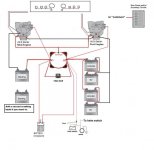
First schematic:
This shows a single MBSS for a twin engine scenario and assumes that the HLBB is Starboard side.
The 500 Amp 7622 ACR will automatically combine banks for Stbd side cranking.
It will also allow the HLBB side to take advantage of the Port engine alternator charge rate while under way.
Note that the O/B Charger leads connect to the #1 and #2 terminals of the MBSS, and not to the battery terminals. (A pet peeve of mine!)
Also note that I show a new dedicated fuse/breaker panel for Accessories, etc.
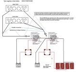
Second schematic:
This shows 2 MBSS's, and 2 cranking banks.
I'm not showing the fuse/breaker panel for Accessories, ACR nor the O/B Charger connections, but these can be installed similar as in the first schematic.
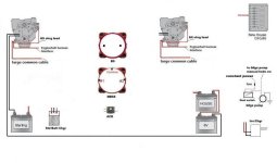
Third schematic:
Here I've shown 2 MBSS's and a means for both "manual", "helm switch activated", and/or "automatic" combining.
This is very similar to how I have my own twin engine boat set up.
My boat is considerably smaller, but I believe that this can work for your 38.


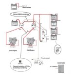
Forth one shows some icons that you could shift around if you wanted to draw up a schematic.
 

Attachments

  • Melenconn MBSS Drawing 6.jpg
    Melenconn MBSS Drawing 6.jpg
    55.1 KB · Views: 261
  • Dual helms dual engines.jpg
    Dual helms dual engines.jpg
    64.9 KB · Views: 150
  • MBSS Batt and Engine icons for Meleconn.jpg
    MBSS Batt and Engine icons for Meleconn.jpg
    32.3 KB · Views: 92
  • Twin Engine Battery schematic for Tom.jpg
    Twin Engine Battery schematic for Tom.jpg
    49.5 KB · Views: 927
Last edited:
Rick, thanks once again. Yesterday spent in the bilge tracing wires. It would now appear that the main positive to the board comes off the engine breaker you pictured. Port red, stbd black grey, both are positive. This feeds the 12v panel and from there to the house and start. Disconnecting the red disables the start and on that panel are also the two engine switchs. The keys at the helm only are active when those switches are in the ON position. So back to the drawing board re start/house.
After some discussion with a friend who has the same engines in a Marinette and considering the complexity of the boat wiring we have come to the conclusion that two banks, each start/house, but seperated for use and charging purposes might be the route. Coupled with a new bty charger and all the associated items it would be economically a more viable route to take. In this regards I am thinking about the ProIso Charger, or Victron. As well I will likely upgrade my alternators and associated regulators. Given that the boat was basically 120v dock to dock, with an afternoon anchor 12v to manage the fridge, this seems to be the best fix. We spend all our time at anchor only going to dock for fuel and food. We even live off the water of our fresh clean Georgian Bay.
Your first and third schematic look promising for sure. My whole thought is KISS, I only wish the builder and others worked the same principal.
We will be out in BC next week, not boating however, thanks once again, your insight was more than helpful. Bill.
 
Greetings: Find attached the 12v wiring diagram for a CC Cat 381. Note that the drawing is for hull # 982-985, and the diagram was provided from one who owns a 1986. My 1987 models the wiring to a letter.
The only issue still remains as to why CC used wire 45-46 to draw power from the breaker. Still do not understand why CC has done this. As for a start/house system I will build two, and switch daily between. A rewire is out of the question. Just add AH to statisfy the daily needs and charge the bank at rest.
One point that I did not know or share dealt with the genny. The onan 6.5 was running to my ear like a top. However upon investigation I determined that she was putting out in excess of 180 volts at more than 77 hertz. The NORCOLD just shut down with that power. So using a simple household electric monitoring device I reset the hertz and all is well. The device is available from most hardware stores, but you must ensure that it will read hertz. I found one for under 15.00$ imported by Hampton Products www.hamptonproducts.com 1-800-562-5625. A device we can all use as I think that many genny's need a tuning at least once a year.
See the attached, if not send me a mail [email protected] and put 381 12v wiring diagram in the subject. Regards Bill PS: Unable to upload pdf file, so send me a msg.
 
As to your query about why they tapped at the breakers for circuits 45 & 46...

Here's my thoughts - they tried to follow best practices by finding a "protected" source to feed the panels and the breakers at the engine were the low cost solution. They "screwed up" on the STBD by using because they didn't use a red wire.

Those are the circuits to "lift" from the engine breakers to add a dedicated house bank...you would then only need to add your device of choice to enable charging the house bank from the alternators on the engines.
 
Rick,

I have a 31' CC Commander, 1969 with twin Crusade 270s. Which wiring diagram would you suggest for me as I add a house bank?

Thanks in advance.

Steve
 
Greetings Steve. I hope your winter is going well. As to wiring. Take a long look at reply #5. The data provided fits the bill. If your CC is like mine likely it was a dock vessel, needed 120 to survive. However, you have two routes, a seperate house and start,with a parallel switch to that you will always have a bty source, or two banks which you draw from on alternating days. I think in your case seperate is the answer. Unless you are committed to bties, take a long look at using 6 volt rather than 12. Better amp hrs for sure.
I have just acquired a new charger, 40 amp Blue Seas, and will install that on my boat. As to the bty bank two, a mix start/house as the wiring becomes too complicated to do otherwise. I will install ACR units and monitor and operate from one bank for 12 hours and then charge. Banks will be two 31 12v deep cycle btys providing I hope sufficient amps to keep my shared Capt happy. In real terms the only issue is the fridge and power to bilge pumps. The genny is seperate except through the bty charger. Keep me involved as I will you on the process come spring. Bill
 
Bill, thanks for the reply. I loved the wiring diagrams as they have given me all manner of ideas. I will likely go with dedicated starting batteries to each engine with a meter to view the charge on each one. One engine will be used to charge the house batteries (via a switch along with a solar panel and my small generator if needed). Like you I am setting mine up for self-sufficiency at anchor with major power draws with the engines off being the fridge, fans, and anchor light. As for house batteries, I am sold on 6volt golf cart batteries. Right now the problem is sorting out the wiring as I've had several problems due to a previous owner's poor wiring skills.
 
Back
Top