Logo

318 reverse rotation already assembled

joeteel

New member
rebuilding a 318. Pistons needed replacing because valves beat em up pretty bad had mahine shop press out rods and heat in new pistons when they rework heads and magna flux block.I think I may have screwed up by putting the F on the pistons fwd. ( read about it on some old forums) as one would do

Whats the chances of unboltin rod caps and turnin 180 degrees
I do not know much about the RH Rev Rotation 318, but can suggest to you that IF the piston wrist pins are offset (as they are with the SBC's) the offset must be correct for a RH Rev Rotation engine.
Connecting rods are also directional with regard to their positon on the crank journals........ so flipping the pistons/rods around is likely going to cause a major issue.

I'd take everything back to the machine shop, and ask them. If need be, ask to have the pistons turned around on the rods.
But ONLY if this does not cause an issue with valve reliefs, etc, etc.


For example..... this style piston is ambidextrous.
One p/n fits all 8 bores. These can be turned around without any issues.


Likewise with this style.


This piston above will not offer you any Quench Area...... perhaps something to consider for a Marine Build with Chrysler's wedge style combustion chambers (very similar to the SBC chambers).


Here's what the 318 chambers look like.
Note the quench surface.
Why not take advantage of this and give yourself a good quench dimension????


Here's a generic LCQ style piston used with a wedge style combustion chamber.
As you can see, if this piston is turned around, it must be used on the opposite bank.


See this thread re; the SBC and a quench build.... start at page #8.


.
 
Last edited:
the pistons I have are the ones w/ 4 valve reliefs but noticed different sizes between intake and exhaust. Should I feel comfortable turning rod 180 so the dot and the F mark to the back of block now. I spoke the machine shop and he said he put rods back just like they came off but was surprised to install dot or F to the back getting 2 different opinions and its boiling down to 50/50. there is a stamp on the caps I remember somewhere to put these #s out ?????
 
Joe, with this style cylinder head ...... Exh/Int/Int/Exh/Exh/Int/Int/Exh ... and with unequal sized valve reliefs (which is good IMO) ....... this engine requires two piston p/n's.

0810phr_10_z+chrysler_318_engine+cylinder_heads.jpg


Let me take a stab at explaining this.

Here are your cylinder numbers and firing order.


I was limited to piston images.... so I'm unable to begin with #1 cylinder.

If I'm thinking correctly, the piston that was previously in #3 bore, would now move to #6 bore, but only when turned around and reconnected the #6 connecting rod.


attachment.php


(Disclaimer..... I did this quickly.... hope I didn't boo boo. Plus, this is predicated on the 318 piston wrist pins being offset.)

BTW, I made the assumption that the under-cut valve reliefs were for the larger diameter Intake valves... (not necessarily cut for a larger Exhaust valve lift).
If I'm incorrect on this, just assume or pretend that they are, and the rest will still apply.

Also, and just an FYI, if we were to use full dished style pistons, or double valve reliefs of equal size, none of this would be relavant.
We would just turn the pistons around on the same connecting rods.
 

Attachments

  • Chrysler 318 360 RH Rev Rotation piston pin offset.jpg
    Chrysler 318 360 RH Rev Rotation piston pin offset.jpg
    51.7 KB · Views: 4,435
Last edited:
The connecting rods are machined to go on the crank one way. The wrist pin must be removed and the piton rotated 180*.

will
 
The connecting rods are machined to go on the crank one way. The wrist pin must be removed and the piston rotated 180*.

will

Will, I would agree with this if these are abmidextrous.
Joe's comment here.
joeteel said:
the pistons I have are the ones w/ 4 valve reliefs but noticed different sizes between intake and exhaust.
Will, do you know if these are capable of being turned around on/for the same cylinder?
I haven't touched a Chrysler 318/360 for years.


.
 
Aargh! Yes, the pistons have to come off the rods, be reversed, then reassembled. The "F" mark then goes to the rear.

If this is not done, the motor will be very noisy at idle and the pistons/ rings will not last as long.

Jeff
 
Aargh! Yes, the pistons have to come off the rods, be reversed, then reassembled. The "F" mark then goes to the rear.

If this is not done, the motor will be very noisy at idle and the pistons/ rings will not last as long.

Jeff
Jeff, I fully agree. The "F" mark must now face rearward, and for the very reasons that you point out.

I guess that my questions are:


1 .... knowing that Joe's pistons are four valve relief.... (I'm assuming this style, but with unequal sized valve reliefs).....


...... can the #1 cylinder piston simply be reversed and re-installed in #1 hole?

IOW, are the valve reliefs allowing this piston to be ambidextrous in this fashion?


2.... because of the four valve reliefs and with Exh/Int reliefs of different sizes, does #1 now need to be swapped with a differen bore (more or less as per my image in post #4 where I'm showing a LCQ style piston)?


I'm curious.... as I don't have the Chrysler 318/360 experience that many of you guys have.


.
 
Last edited:
The 4 reliefs are so the same piston can be used for the left or right banks.


Think about it!

Jeff
Jeff, Joe suggests that the Intake valve reliefs are cut larger than the Exh reliefs.

If so, and if clearances have been predicated on this........ it causes several points of attention:

1..... 2 piston p/n's are required for either LH or RH Rotation engines.

2..... #1 piston's orientation would be same as the #2 bore for a LH Rotation engine.

3..... the "F" notch would be facing forward....... wrist pin offset and the valve reliefs would be correct (FWD Reliefs = Exh..... Rear Reliefs = Int), etc. and again...., for a LH Rotation engine.

4.... cylinder #'s 3 & 4 and 7 & 8 would require the other p/n pistons (in order for the valve reliefs to be correct).


My question was for the Rev RH Rotation engine:

When turning the pistons around for a RH Rev Rotation engine..... and with this double relief piston, which bores do the pistons NOW need to be installed in?

I believe that it's clear that #1 cannot simply be turned around for use in bore #2. (look where the large reliefs would be)

Looks to me like #1 would need to be changed on the connecting rod for use in either #3 or #4, if we want the valve reliefs to be correct.

NOW.... if the larger sized Int valve reliefs are not an issue, then my question is moot!
 

Attachments

  • Chrysler 318 360 RH Rev Rotation piston pin offset 2 .jpg
    Chrysler 318 360 RH Rev Rotation piston pin offset 2 .jpg
    37.3 KB · Views: 187
Last edited:
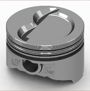
Joe, using a SBC for example (if I may) ...... my point is/was..... with a piston like this, it's ambidextrous with regard to the cylinder bores.

The valve reliefs are equal in size, so one piston p/n fits all 8 bores....... "F" symbol facing forward for LH rotation.


With this style single valve relief "quench" piston (equal sized reliefs), 2 p/n's are required.... right bank... left bank...... "F" symbol facing forward for LH rotation.


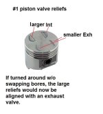
With this style single valve relief "quench" piston (unequal sized valve reliefs) 4 p/n's are required...... 2 each right bank... 2 each left bank...... "F" symbol facing forward for LH rotation.


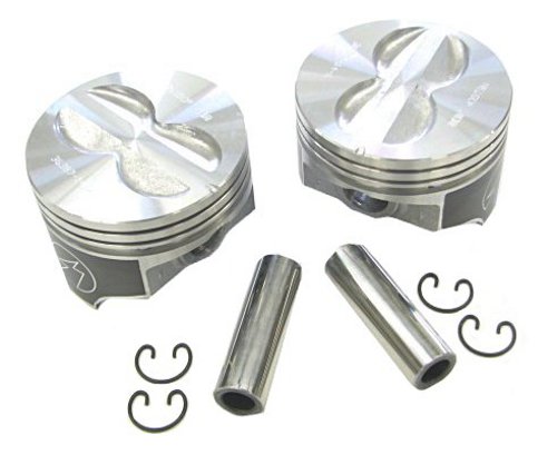
With a LCQ (LCQ = low compression quench) style piston (with unequal sized valve reliefs), 4 p/n's are required...... "F" symbol facing forward for LH rotation.


This is due to the valve orientation of the SBC cylinder heads ........ of which is similar to the 318/360 cylinder heads.
Exh/Int/Int/Exh/Exh/Int/Int/Exh

0810phr_10_z+chrysler_318_engine+cylinder_heads.jpg


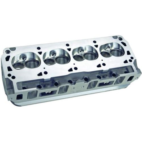
If this was a 5.0L or 5.8L Ford valve arrangement, things would be quite different.
Here we see Exh/Int/Exh/Int/Exh/Int/Exh/Int.


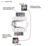
Point being.... look carefully at your valve reliefs while you are turning the pistons around as to correct the wrist pin offset for a REV RH Rotation.
IOW, it may not be as simple as turning #1 around and re-installing on #2 connecting rod.

Your machinist/engine builder will know exactly what to do.


BTW, I'm fairly certain that your 318 connecting rods are directional within one crankshaft journal.
If so, this is why you can't simply flip them around.

Perhaps Jeff could confirm this one way or the other.


.
 
Last edited:
"BTW, I'm fairly certain that your 318 connecting rods are directional within one crankshaft journal.
If so, this is why you can't simply flip them around."


Just curious Rick, what makes you believe this??
 
RicardoMarine said:
"BTW, I'm fairly certain that your 318 connecting rods are directional within one crankshaft journal.
If so, this is why you can't simply flip them around."
Just curious Rick, what makes you believe this??
Dave.... that's a fair question!

Again.... I'm making what may not be a safe or close comparison here.
The GM engineers want two opposing cylinders to be as close as possible to the center of the shared crankshaft journal. Yet at the same time, they want each rod end beaing surface to be as wide as feasible.
The rod bearing surface then extends towards the crankshaft throw.

Where he's showing the feeler gauge, the rod centers are closest together.
Note the extended bearing surface towards the crank throws.
These connecting rods can NOT be flipped around.

I'm asking Jeff or any of you guys, if the Chrysler 318/360 is similar to what GM did with the SBC.
If not, and if these rods can be turned around, then it becomes a moot point.


Last edited:
I believe Mopar used "oil squirter" rods in their 318/ 360. If so, these can not be reversed or the oil won't hit the bottom of the pistons.

I stared at that 4 relief piston and can't see a difference in notch sizes. Sorry. It would make NO sense at all to make one notch larger than the other, THEN use 4 notches, for the other 2 would never be needed, right?

Jeff
 
  1. I believe Mopar used "oil squirter" rods in their 318/ 360. If so, these can not be reversed or the oil won't hit the bottom of the pistons.


  2. I stared at that 4 relief piston and can't see a difference in notch sizes. Sorry.


  3. It would make NO sense at all to make one notch larger than the other, THEN use 4 notches, for the other 2 would never be needed, right?

Jeff

  1. Good point, and again, this is where you guys would know much more about this than I would.


  2. Those were example pistons only that I pulled from a Google Search. Joe did not provide that image.
    However, he did confirm that the reliefs were unequal in size.

  3. I'm not sure how to repond to that, other than to say.... that in the 70's GM began using that silly, stupid, no good full dished/double relief piston (SBC) for emmission control standards, and they continue using it today..... even in the Marine SBC! :mad:
    One piston p/n fits all 8 bores.

    The Chrysler double relief (unequal reliefs) would require 2 p/n's.

    As per the LCQ piston (unequal reliefs) that I show, 4 p/n's are required.
    This is the price we pay for creating a good quench effect..... and it's well worth doing, IMO.

I realize that comparing the SBC to the 318/360 is not an Apples/Apples comparison....... but I don't know how else to show the relevance.
Both do use a wedge style chamber cylinder head that offers a quench surface.


.
 
Aargh! Yes, the pistons have to come off the rods, be reversed, then reassembled. The "F" mark then goes to the rear.

If this is not done, the motor will be very noisy at idle and the pistons/ rings will not last as long.

Jeff


Jeff you and Ricardo are wrong. I just spent hours researching this because I was concerned about how confident you were with your answer. You are mistaken. Chrysler LM318 and LM360 engines have symmetrical thrust faces on either side of the piston. Because of how it connects to the rod the piston notch ALWAYS FACES FORWARD regardless of engine rotation. See figure 37 page 41.

https://www.manualslib.com/manual/1007590/Chrysler-Lm-318.html?page=41#manual

I have responded to your comments in shellback's thread.

Suggestions:
.... Start a new thread on this topic.
.... Perhaps title it: "Chrysler 318/360 piton wrist pin offset debate... offset or no offset?"
.... Ask for comments.
.... be polite and keep it civil.

Otherwise, you are simply hy-jacking Joe's and shellback's threads that you have been posting to.


.
 
Last edited:
I fully concede that i was wrong and jeff and ricardo were correct. After alot of back and forth and incorrect information provided to me by a local marine engine rebuilder that rebuilt both of my engines and does this everyday professionally i found out my source was wrong and these gentlemen were correct. I apologize and make no exuses for saying these guys were wrong when they were in fact correct. Sometimes you have to swallow your pride and admit when you’re wrong. This is one of those times. My apologies are offered and i hope they are accepted. Notch goes towards the rear on a reverse rotation engine.
 
I fully concede that i was wrong and jeff and ricardo were correct. After alot of back and forth and incorrect information provided to me by a local marine engine rebuilder that rebuilt both of my engines and does this everyday professionally i found out my source was wrong and these gentlemen were correct. I apologize and make no exuses for saying these guys were wrong when they were in fact correct. Sometimes you have to swallow your pride and admit when you’re wrong. This is one of those times. My apologies are offered and i hope they are accepted.
Thank you, Mike. Your apology is accepted.


Notch goes towards the rear on a reverse rotation engine.
Just to clarify;

...... a double valve relief F/T piston w/ equal size valve reliefs can be reversed.

...... a double valve relief F/T piston w/ un-equal size valve reliefs can be reversed, but will need to swap cylinders and/or banks as to be oriented correctly per Int/Exh valve location.
In other words, it will not go back into the same cylinder as though it was a Std LH Rotation engine.

...... a full dished piston w/ no valve reliefs can be reversed.

...... a full dished piston w/ double and equal sized valve reliefs can be reversed.

...... a LCQ style piston w/ equal size valve reliefs can be reversed, but will need to swap cylinders and/or banks (due to the quench surface).
In other words, it will not go back into the same cylinder as though it was a Std LH Rotation engine.

...... a LCQ style piston w/ un-equal size valve reliefs can be reversed, but will need to not only swap banks (due to the quench surface), but will need to be oriented correctly per Int/Exh valve location.
In other words, it will not go back into the same cylinder as though it was a Std LH Rotation engine.

MikeCinci said:
incorrect information provided to me by a local marine engine rebuilder that rebuilt both of my engines and does this everyday professionally i found out my source was wrong and these gentlemen were correct.

Regarding the above.......... I have a question;
Did this Engine Re-builder build your engines correctly, or incorrectly?


And Mike, in the past when I've been in error here, the members forced me to stand in the barrel for one week.
You may also need to serve your time in the barrel!
:D


.

 
Last edited:
I am glad y'all got that straightened out between you..Y'all had me totally confused . I currently have my LM318 reverse drive tore down, new bearings etc ready to go in, cleaned and ready to put back together.. I kept everything in order as it came out.. this is the reason I was following your thread.. on my pistons .. the F and notch on 4 of them are on the rods facing all the writing on the rod... the other 4 have the F and notch facing the side of the rod with no writing.. so what your saying is as long as I put the F and top notch to the rear of the motor I will be in good shape.. I made sure I kept them on the correct side and correct cylinder hole but I got them turned around and confused myself on which way the notches faced... You guys probably saved me a lot of trouble by designating the F&notch to the rear on a RH motor.. Thanks..
 
............
I currently have my LM318 reverse drive tore down, new bearings etc ready to go in, cleaned and ready to put back together..
Question:
Are you suggesting that you have an "opposite of engine rotation" transmission?
If so, that engine may be standard LH Rotation.


I kept everything in order as it came out.. this is the reason I was following your thread.. on my pistons .. the F and notch on 4 of them are on the rods facing all the writing on the rod... the other 4 have the F and notch facing the side of the rod with no writing.. so what your saying is as long as I put the F and top notch to the rear of the motor I will be in good shape..
That would be for a REV RH Rotation engine.

I made sure I kept them on the correct side and correct cylinder hole but I got them turned around and confused myself on which way the notches faced...
Keep in mind that the connecting rods must still be in the correct orientation for the crankshaft journals.
In other words, unless you know which rods can be swapped to another crankshaft journal, you do not turn the entire piston/rod combo around 180.


You guys probably saved me a lot of trouble by designating the F&notch to the rear on a RH motor.. Thanks..
 
Minus the wrist pin offset (shown here for a Std LH Rotation), the spurt hole orientation must be as shown regardless of engine rotation.

 
Ok what is more important... the squirt hole or the notch&F position.. keep in mind this is a RH/Reverse Rotation engine.. in order for me to put the squirt hole inward toward the cam.. the notch and F on the piston would have to face the front... and I see no difference on this chamfer your talking about... . and from what I have been reading on the past posts.. the notch and F always face the rear on a RR engine..this is a NAPA motor with only 4 or 5 hours on it .. intake gasket leaked the 2 gallons of antifreeze into the oil ... so the pistons have never been off the rods and don't need to be.. I'm not changing the rings,, just fresh bearings since I had it tore down.. I have built Toyota 22R engins but never one of these so kinda new to this reverse stuff... for some reason I cannot post pictures... ???
 
Last edited:
...........
Ok what is more important... the squirt hole or the notch&F position..
Both are equally important.

keep in mind this is a RH/Reverse Rotation engine.. in order for me to put the squirt hole inward toward the cam.. the notch and F on the piston would have to face the front...
Not true!
If changing from a Std LH rotation assembly to a REV RH rotation assembly, you would need to remove the wrist pins, remove the rods from the pistons and reverse the F notch so that they now aim towards the rear.
The spurt holes and journal faces will remain correctly orientated.


and I see no difference on this chamfer your talking about... .
Look closely at the crankshaft journal end of the rods, and take another look at the image in post #25.
They are directional regarding which side of the rod faces the outside of the crankshaft journals.


and from what I have been reading on the past posts.. the notch and F always face the rear on a RH Rotation engine..
Yes...... that is necessary to position the wrist pin offset correctly.

I really don't think that diagram from Auto Zone for a standard rotation engine applies to my engine...???
With regard to the rods and their position on the crankshaft journals, yes it does.
As long as the rods are installed on the crankshaft correctly, the crankshaft and connecting rods don't care which rotation they will be turning.
The pistons do care with regard to the wrist pin offset when used in either rotation engine.

Std LH Rotation.... F notch facing forward.

REV RH Rotation..... F notch facing rear.
With the Chrysler 318, the rods, their spurt holes and the chamfered areas remain positioned the same.


Some people tend to ask the same questions in hopes of finding an answer that suits them.
Try not to get caught up in that.
 
Last edited:
LOL...as far as removing the wrist pins from the pistons .. not gonna happen... I just took this engine apart.. it was built by NAPA.. if the notch and F are going to be facing rear.. the squirt holes are facing toward the outside of the block... if the the notch and F are facing forward the squirt hole are facing inward.. I didn't build it this way.. it has never been into before.. it has maybe 4 hours on it.. are you telling me NAPA built it wrong... and also ... the offset in the wrist pin with the notch to the back stays the same on both sides.. according to the way NAPA built it.. I would think the offset would also flipflop... to stay equial... now I am really confused on how they go... notch to the back .. squirt holes out... notch to the front.. squirt holes in... wrist pin offset the same on both sides unless I reverse the the notch and F on one side.. one to the front, one to the back... It absolutely ran perfect when I took it out... and was so quiet the raw water pump made more noise than the engine.... wish I had paid just a little closer attention when I took the pistons out as far a the notch goes... I have them laid out to go back in the same cylinder.. but this notch, F, offset, chamfer crap is about to put me over the edge...
 
Last edited:
..................
LOL...as far as removing the wrist pins from the pistons .. not gonna happen... I just took this engine apart.. it was built by NAPA..
if the notch and F are going to be facing rear.. the squirt holes are facing toward the outside of the block...
Withe that scenario, how will the camshaft receive adequate splash lubrication?

if the the notch and F are facing forward the squirt hole are facing inward..
With that scenario, the camshaft will receive the proper splash lubrication, but the wrist pin offset will be INCORRECT!

I didn't build it this way.. it has never been into before.. it has maybe 4 hours on it.. are you telling me NAPA..............
It looks like you stopped short on that one.


Suggestions:

Join several other Marine forums (who have a Chrysler Marine section), and pose the same questions.

Contact several Marine specific engine re-builders and ask the same questions.


Perhaps go back and read these responses:

Will post #5
Jeff post #7
Dave post #12
Mike corrects himself in post #18
you admit being confused in post #18
Ed post #24.
My posts throughout the thread.

Can we all be wrong?


It's your engine, do as you wish.
 
Last edited:
Back
Top