Logo

Help - Where to install heater water lines?

Fred.... I'm trying my best to make this easy for you, and so that you end up with a working system.

I may be get confused in here... the 9:00 O'clock port is the one I plugged the return.
Correct!


.. isn't this hose #8 going to the circulation pump and would be a supply?
NO..... this is on the suction side.... and is schematically similar to the 9:00 O'clock suction port.


Anyhow, I got a tip today that I will try... I was told that there are a couple reasons I may not feel the hose at the heater end getting warm... I was told that I may have air trapped in there therefore it won't pump water through the heater
To a degree, this should self purge, and in particalur with an "open" system (aka Raw Water Cooled).

and also that I should check if the connections on the heater aren't inverted..
The heater core's inlet/outlet should be ambidextrous....... although......... (see next)

I thought that it wouldn't matter but I was told it matters, that I should connect the feed in the bottom and the return on the top.
Intuitively that sounds correct and makes sense. It will work either way.


I will check the connections and will disconnect the bottom hose and will blow water through the top hose to make sure I clear any air trapped in there.
That wouldn't hurt to do.


Basically, everything that you need to know has been re-capped in post #32.


.
 
Last edited:
Hi Rick,

I was away for a couple days but yesterday I decided to check the hoses from the heater end... make sure that was no air trapped and that water was flowing... I unplugged one hose (one coming from the 9' of circ. pump). Run the engine and there was water coming from the supply hose and it was running through the heater and water was coming out on the other end where I had unplugged the return however, I was surprised that I also had water running from the return line.

I put my finger to plug the return line from the circulation pump and when I gave a little gas (increased the RPM) the pressure built up on the return line and I had to remove my finger and water was running.

I think that both lines are working as a supply therefore there is no circulation.

Thoughts?

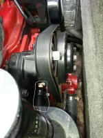
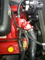
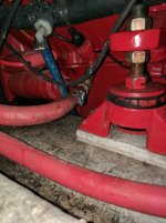
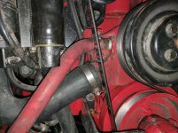
Here is the pictures where they are plugged.
20130428_151231.jpg20130428_151203.jpg
 
Last edited:
Fred.................

Hi Rick,

I unplugged one hose (one coming from the 9' of circ. pump). Run the engine and there was water coming from the supply hose and it was running through the heater and water was coming out on the other end where I had unplugged the return however, I was surprised that I also had water running from the return line.
This is not a captive system like a closed cooling system would be.

With the 9:00 O'clock port disconnected, you may see water flow due to the nature of the Raw Water T-stat housing configuration.
Once the system is connected, it should realize the mild pressure differential.

That said.... see my next comment.


I put my finger to plug the return line from the circulation pump and when I gave a little gas (increased the RPM) the pressure built up on the return line and I had to remove my finger and water was running.
Check your manifold/elbow sea water transfer ports......... they may be restricted via rust scale and blockage!

If they are restricting sea water flow, it may be preventing the sea water pump to easily supply water to them, and out the exhaust.
In which case it may be possible that the sea water pump is attempting to over-pressurize the engine side of the system.


I think that both lines are working as a supply therefore there is no circulation.
See above.

Thoughts?
I've been involved with the SBC for over 45 years. I know this engine fairly well.
I may not have all the answers, but I feel very comfortable in what I've been suggesting here.


Here is the pictures where they are plugged.
Image #1 is correct.
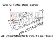
If image #2 shows a connection to the front intake manifold port (within the cross-over chamber), it too should be correct.

(see attached image)

View attachment 6684View attachment 6685
 

Attachments

  • Volvo Penta later intake manifold port.jpg
    Volvo Penta later intake manifold port.jpg
    44.6 KB · Views: 154
Last edited:
SOLVED!

Rick, you were absolutely right from the beginning on all the connections. The reason the heater wasn't warming up is because I was testing it at home with the hose connected as the water source. As soon as I put the boat in the water, with the volume of water, after the boat engine temperature reached above 100F the air was already coming warm. When boat is operating the temperature is around 150 and all hoses got a nice warm air.

Thank you for your help!
 
I followed this discussion since the beginning. Excellent job from Rick ! as usual precise info with illustrations and so on. A great bravo to Rick !!!
 
Ricardo,
Can I connect the supply where this plug is (beside number 19 on the figure)
http://www.marinepartseurope.com/en/volvo-penta-explodedview-7746090-26-10059.aspx


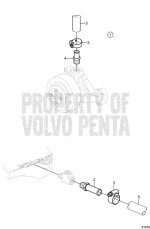
I can confirm that the Penta diagram below illustrates the correct heater connections. I have a boat that has a factory installed heater. I came here to determine how to properly reconnect it. The Penta illustration below showed me where to look for the coolant connections. Upon matching the factory installed hose lengths and the obviously plugged ports I was able to confirm the illustration. The hot coolant supply connection is the nipple number 2 in the Penta illustration located low in the middle of the block on the starboard side. The coolant return connection is nipple number 4 in the Penta illustration on the water pump however mine is not connected to the top but rather a port on the starboard side of the pump. I assume either is equal for functionality. The Penta illustration combined with the assumption that Reinell would connect the heater in accordance with manufacturers standards I believe this to be the best configuration for the Penta 5.0GXi.


21979.jpgIMG_20170326_193645sm.jpgIMG_20170326_193629sm.jpg
 
Last edited:
First off....... this thread was started in April of 2013...... which makes it almost four years old.
(it is always best to start a new thread for your topic)
But since we're here........


I can confirm that the Penta diagram below illustrates the correct heater connections.
I disagree.......... it demonstates an alternative method.
Perhaps read post #2 again!

I have a boat that has a factory installed heater. I came here to determine how to properly reconnect it. The Penta illustration below showed me where to look for the coolant connections. Upon matching the factory installed hose lengths and the obviously plugged ports I was able to confirm the illustration.
Again, this is an alternate method.

The hot coolant supply connection is the nipple number 2 in the Penta illustration located low in the middle of the block on the starboard side.
I could not suggest doing this!
The warmest engine coolant (exiting the cylinder block/heads) will be from the intake manifold port where the coolant has passed through both the cylinder block and the cylinder heads.
The thermostat holds back coolant giving it the mild positive pressure that is necessary for a good working Cabin Heater or Water Heater!
The CH or WH must have the necessary "balance" between pos and neg pressure. With out it, we will not see good coolant flow!

(see this image again)
[url]http://www.marineengine.com/boat-forum/attachment.php?attachmentid=6685&d=1367259588[/URL]

The coolant return connection is nipple number 4 in the Penta illustration on the water pump
That would be the engine circulating pump.

however mine is not connected to the top but rather a port on the starboard side of the pump.
That would be correct!

I assume either is equal for functionality.
Not quite, but either will work!
These ports are directed into the suction area of the circ pump body.

The Penta illustration combined with the assumption that Reinell would connect the heater in accordance with manufacturers standards I believe this to be the best configuration for the Penta 5.0GXi.
It may be the only configeration if the Intake Manifold does not offer the port prior to and to the Stdb side of the T-stat housing.


NOTE:
The cylinder block port shown being used for the coolant supply (first and second images) is only 3/8" TP.
The 3/8" TP threads and corresponding hose fitting will restrict coolant flow.

The intake manifold port (not shown) is typically 1/2" TP and will be much less restrictive.

The third image shows the correct suction port connection.


View attachment 15103View attachment 15104View attachment 15105
 
Last edited:
Back
Top