Logo

Chrysler M440 Right hand (reverse) Rotation Intermediate Gear

TonyJ1961

Contributing Member
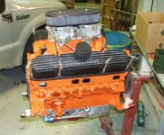
I am looking for an intermediate gear for my M440B right hand rotation engine. Apparently, MOPAR no longer supports this type of gear. It's a left hand cut gear and, of course, is the opposite of what is used in the automotive world.

If I can't find anything, I will probably have a few gears made using my original for a pattern.

Anyone know where any can be found?
 
Hi
What are you referring to as an intermediate gear? if you can be specific I may have one. Is it the rare gear drive on the cam or are you referring to the oil pump drive gear? Let us know.
Dan
 
The oil pump drive is referred to as an Intermediate Gear. A standard rotation engine has a right hand cut. That is it's a bevel cut spur gear that begins at the upper left and goes to the lower right. Reverse rotation engines are the opposite: they start at the upper right and go to the lower left. This allows for the oil pump to turn in the proper direction no matter which way the cam turns.

The Intermediate Gear is driven off the cam gear and drives the oil pump and the distributor.
 
Oh it's not worn out, I am building another engine and I don't want a failure. My plan is to build a 500CID, 500hp M440 based engine. I just don't want a failure of the Intermediate Gear to cause and oil failure.
 
What are you doing for a camshaft?

The intermediate shaft will see the same load as a stock motor. If you worried about it, go with a crank trigger/coil on plug ignition system and loose the distributor.
 
Last edited:
I am sure that I have at least 1 reverse engine distributor drive gear. I would not consider building a reverse engine these days. Change transmissions to reverse the output shaft not the engine. Both engines in my 33 are right hand and both props are right hand. I cannot tell the difference from reverse rotating drives. With the parts being obsolete just build standard rotation. If you want the gear I will not be back home till spring. I also have a set of left and right electronic distributors and the thrust spacers from a set of left and right engines if anyone needs them.
Dan
 
Keep me in mind, Dan. I would be interested in the Right Hand distributor and a drive gear. I want to do a right hand engine because it's different. Anyone can do a left hand engine. YOu can shop the hi po web sites, even the MOPAR sites and build a formidable lefty. A right hand engine is something special.

Call me a kook (okay, I'm a kook!), but I have a sentimental attachment to the right hand marine engines.
 
It's not the distributor I am concerned about. It's the shaft shearing, or gear stripping and losing the opil pump. IF the distributor goes, the engine shuts down. If the oil pump goes, the engine shuts down, too...just makes more of a spectacle of itself when it does.
 
Keep me in mind, Dan. I would be interested in the Right Hand distributor and a drive gear. I want to do a right hand engine because it's different. Anyone can do a left hand engine. YOu can shop the hi po web sites, even the MOPAR sites and build a formidable lefty. A right hand engine is something special.

Call me a kook (okay, I'm a kook!), but I have a sentimental attachment to the right hand marine engines.


Were all little 'kooky' Tony or we wouldn't be running Chrysler's....!

Jack
 
You gotta point, Jack. But for all around, pure, raw POWER...it's hard to beat a big block Chrysler. And besides, any 4 year old with a screwdriver and pliers can build a Chevy. Chrysler's and Ford's take a little skill.
 
The oil pump drive is referred to as an Intermediate Gear. A standard rotation engine has a right hand cut. That is it's a bevel cut spur gear that begins at the upper left and goes to the lower right. Reverse rotation engines are the opposite: they start at the upper right and go to the lower left. This allows for the oil pump to turn in the proper direction no matter which way the cam turns.

The Intermediate Gear is driven off the cam gear and drives the oil pump and the distributor.
Tony, if you are building an engine from scratch, why not purchase a camshaft profile for double gear drive (not chain & sprocket drive).
The double gear drive will rotate the camshaft in the Standard LH rotation direction, even while the rotating assembly spins Reverse RH rotation.
With this camshaft drive arrangement, the camshaft drive gear cut (the gear that drives the distributor and oil pump) will be the same as the OEM Auto Engine.
Yes/No???

The intermediate shaft will see the same load as a stock motor. If you worried about it, go with a crank trigger/coil on plug ignition system and loose the distributor.
He still needs to drive the oil pump in the Standard rotation direction.


.
 
Tahoeover,

The cut of the intermediate gear will determine the rotation of the oil pump. Essentially, the bevel cut is used to keep the oil pump turing in the right direction, as if the amny engine is a standard rotation engine.

As for gear drives, I am moving toward a standard rotation engine. To obtain a reverse rotation grind that I need for my application, I would need to go with a custom ground cam. Normally not a problem...except for a right hand rotation. LSM Engineering is the only company willing to do so. They would whittle a custom cam from a piece of steel. Unfortunately, the cam would cost about as much as a set of aluminum cylinder heads (about $2K). The cost to purchase a left rotation prop is much cheaper (about $300) and I simply rotate the front pump in my Velvet Drive about 120 degrees.

Problem solved.
 
Tony, is this for a twin engine boat?
If so, I don't think that you'll want a twin engine application driving the the same hand propellers.
In most applications, the Stbd side should spin a RH prop, Port side should spin a LH prop.

If for a single engine boat, I'd forget the idea of being different with a Reverse RH engine....... There's no real value in it.


.
 
Last edited:
Rick,

It is a single screw app. But the boat is originally a right hand rotation. Just trying to keep it original.
 
Tony, OK...., I see now that you are wanting to keep it original.

How about a little more info? Make, year, model of the boat? Which style transmission?
Which type engine orientation..... conventional, or V-drive?

Forgive me for asking, but how is this particular boat builder company determining the engine rotation?
Industry Standard suggests:
If it rotates CW, when viewed from the flywheel end, then this would be RH Reverse rotation engine.
If it rotates CCW, when viewed from the flywheel end, then this would be Standard LH rotation engine.

This would be correct no matter how the engine is positioned in the hull.

No offense intended, Tony..... I'm learning from your thread here.
I'm just not aware of any single engine boat that requires a RH Reverse engine.

.
 
Last edited:
The boat is a 1974 Correct Craft Southwind 20. IT is one of twelve built in 1974 with a Chrysler M440B. So far, I have not any more survivors. Chrysler determines rotation as viewed from the stern looking forward toward the bow. Therefore a right hand rotation would mean the propeller rotates CW as viewed from the stern. My transmission is a Borg Warner Velvet Drive with a 1:1 ratio. This works out to really be about 1:1.1, but it is considered 1:1. IT is a direct drive, so the engine sits at a 12 degree angle so the shaft goes straight through the hull. For even more information, visit www.correctcraftfan.com. This web site is wealth of information to ANY kind of Correct Craft.

Just about all of the early CC's are Right hand rotation. The change was made recently when CC went almost exclusively Pleasurecraft, then even more recently to an all GM engine lineup. (Ford is not building any more marine gasoline engines and Chrysler got out of the game in about 1978 or so.)

Check out CorrectCraftFan.com, it has more history and information that I have in my pointed little head.
 
You are correct when determining propeller rotation. However, engine rotation is always viewed as though looking at the flywheel end. To the best of my knowledge, this is industry standard.

This would mean that if your boat was equipped with a V-drive, and the if the prop was still RH, the engine would actually be a Standard LH rotation.

I wonder if Correct Craft may have thought that a RH propeller was necessary (single engine application) due to the helm location.... ( I.E., LH prop torque would affect a RH helm boat, and visa-versa.)
Hard to say!


I assume that the Correct Craft forum guys can't help you find this part?

Just a thought here:
Tahoerover linked you to 440Source.com who shows the double gear camshaft drive for Power Wagon restorations (crank gear: 1851996, cam gear 1859722.).
Since the double gears turn the Standard LH engine camshaft in the Reverse RH Marine engine direction, wouldn't the intermediate gear (for this application) also work for your purpose?
IOW, can 440Source.com offer this part to you?
(you've likely explored this already!)

I presume that this is the gear you need, but in the reverse cut of this?

!BY135h!!Wk~$(KGrHgoOKiYEjlLmfcsHBKjtkCtR3g~~_1.JPG
images
 
Last edited:
Tahoeover,

The cut of the intermediate gear will determine the rotation of the oil pump. Essentially, the bevel cut is used to keep the oil pump turing in the right direction, as if the amny engine is a standard rotation engine.

I'm all too aware with the issues around this. That is why I asked about your cam plans.

When I built my 500hp 440, I reversed it direction to automotive standard. There is no need to go to a stroker at the 500CID. You can get to 500hp easily with the stock bore and stroke.

Here is the Iski cam I went with:
 

Attachments

  • iski.jpg
    iski.jpg
    12.1 KB · Views: 108
Last edited:
I'm all too aware with the issues around this. That is why I asked about your cam plans.

When I built my 500hp 440, I reversed it direction to automotive standard.
When you say that you built your 440 and reversed the cam direction to auto standard, was this a Rev RH 440 engine?
And by reversing cam direction, your valve train firing order was correct for a Rev RH rotation via a Rev RH Rotation camshaft profile?
And this was done with the double cam gear set?
Therefor the standard intermediate gear could be used?

Tony, I'm not into the Chrysler Marine Engines (although I'm a Chrysler car/truck fan).
I'm one of those 4 year olds, with a screwdriver and pliers, who builds and runs the SBC Marine Engines! :D :D

I'm just following your thread with curiosity.


.
 
Last edited:
When you say that you built your 440 and reversed the cam direction to auto standard, was this a Rev RH 440 engine?
And by reversing cam direction, your valve train firing order was correct for a Rev RH rotation via a Rev RH Rotation camshaft profile?
And this was done with the double cam gear set?
Therefor the standard intermediate gear could be used?

Tony, I'm not into the Chrysler Marine Engines (although I'm a Chrysler car/truck fan).
I'm one of those 4 year olds, with a screwdriver and pliers, who builds and runs the SBC Marine Engines! :D :D

I'm just following your thread with curiosity.


.
I said I reversed the rotation to automotive standard. The whole engine crank and cam. I had to move the rudder as well.
 
I said I reversed the rotation to automotive standard. The whole engine crank and cam. I had to move the rudder as well.

Sorry.... I guess that I misunderstood when you said:
Tahoerover said:
That is why I asked about your cam plans.

When I built my 500hp 440, I reversed it direction to automotive standard.

I was thinking that you reversed the camshaft only (as in double gear drive) with a special Isky profile, and kept the Reverse RH crankshaft rotation.

Had you done so, am I correct in thinking that this would have maintained the standard LH engine intermediate gear????

Just curious!

.
 
I tried, but could not make it work. I still own the cam gear set. I have a roller cam and it requires a bronze gear on the oil pump drive.
 
Tahoe,

You pulled 500hp out of a standard 440? I would be very interested in all your engine specs.

Cylinder head castings? Pistons? I see the Isky cam (will have to download the data.) Intake? Carb (s)? Will a dual carb setup work? (C.O.O.L. factor) Did you use any aluminum parts? Ignition setup? Exhaust manifold setup?
 
Steel crank 440 short block
Eagle H-beam rods with ARP wave lock bolts
Total Seal gapless rings
30 over Arias Forged pistons :http://arias-pistons.myshopify.com/collections/pistons/products/chrysler-400-440-b-rb-crank-4-375-1-320ch
Milodon windage tray
Milodon external oil pick up.
Milodon oil pressure adjuster
Milodon oil pump
Fluidampr Harmonic Balancer
Full balance job
Oil plumbing is all AN12 with a HP1 oil filter housing, huge oil cooler.

Heads are 906 castings with Manley Pro Flo SS valves. 2.14"/1.81"
Full port job by Panella Racing: http://panellaraceengines.com/
They flow around 300 cfm on the intake, 215 on the exhaust
Comp Cams SS Roller Rockers 1.5:1
Iski Roller cam. #165150 Grind
Iski solid roller lifters

Edelbrock CH-28 Dual quad intake
Edelbrock 600CFM 4bbl carbs with progressive linkage
MSD Pro Billet Distributor
MSD Marine Multi spark
Taylor 409 race wires

Glenwood manifolds and risers
 

Attachments

  • Mopar-marine440.JPG
    Mopar-marine440.JPG
    83.3 KB · Views: 110
  • 208299_1654816452716_6811628_n (1).jpg
    208299_1654816452716_6811628_n (1).jpg
    78.8 KB · Views: 82
Last edited:
Tahoe,

This is just what the doctor ordered. I see this is a Vee drive? Mine is a direct. Which Glenwood manifold did you use? I have only found one. Which riser number did you use?

So this is a 30 over 440. That would be a ...c'mon calculator 4.350 pi r squared times stroke times 8 cylinders...445.85 call it 446 CID.

Okay, I guess you can call it a 440. IS that 500 dyno'd horsepower?

Tony
 
I built the engine almost 15 years ago. Things have changed since then, it's much easier and cheaper now!

My cylinder head guy builds six figure engines everyday and he put my set up in the mid 500s. Desktop dyno put me in the high 500s. I was too much of a cheapskate to spend $500 for an hour of dyno time. HP= MEP x CID x RPM/33,000 x 12 x 2


It took me a bunch of trips to the river to get it all sorted out. After I got the engine making good power, I turned my trans fluid black from slipping clutches. The trans was freshly rebuilt, but the pressure regulator was not keeping the clutch pack closed. You need to install a trans temp and pressure gauges! The engine pulls hard to 6k RPMs.

Yes it's a V-drive, Paragon PV-400. I have the engine out to install new stringers and convert over to MPI
 

Attachments

  • m440-500.jpg
    m440-500.jpg
    58 KB · Views: 113
  • 440mpi-sm.jpg
    440mpi-sm.jpg
    76 KB · Views: 94
  • 228576_1703373946623_5898262_n.jpg
    228576_1703373946623_5898262_n.jpg
    29.5 KB · Views: 88
  • 24035_1228049903819_3082035_n.jpg
    24035_1228049903819_3082035_n.jpg
    74.9 KB · Views: 94
Last edited:
HHP= MEP x CID x RPM/33,000 x 12 x 2

Here's a quick explanation of the relationship of the values of this formula. MEP is the theoretical mean effective pressure acting on the piston top through its stroke. Notice that cylinder pressure is divided by the work of 1 hp (33,000 ft-lb). These are the force units. Cubic inch displacement (CID) reflects piston top area and the crankshaft's stroke length, which is divided by 12 to convert the value to feet. And finally, the number of power strokes per minute for a four-stroke engine is the term RPM/2 because the cylinder fires every other revolution.


This equation predicts theoretical horsepower, not brake horsepower. It does not account for the frictional power losses of the engine. When you measure on an engine dyno, you measure the net power output of the engine after all losses. The reason it's good to know the math and physical reasoning behind power generation is that it shows you exactly where to make changes to improve the performance of your engine. If you work with the equation, you'll see that to increase power output you have to increase one of these variables. In other words, you have to increase the mean effective pressure in the cylinders, the stroke, the bore size, or the engine speed.


The most common approach is to increase cylinder pressure in order to increases torque output. To do this you need to add more air and fuel to the combustion chamber and ignite it. That's why tuned intake manifolds, superchargers, turbochargers, and nitrous systems work and part of the reason free-flowing intakes and exhausts work as well. Another popular way to obtain more horsepower is to build a bigger engine. The same cylinder pressure acting on a larger piston surface or through a longer stroke will make more power. And finally, you can choose components that will allow your engine to spin very quickly, producing more power strokes per minute in order to increase power. This approach requires tuning the intake and exhaust flow capability to be tuned so the cylinders have enough fuel and air to generate adequate torque at high engine speeds and tends to reduce torque and power at lower engine speeds.
_________
 
Back
Top