Logo

Twin Chrysler 383 mystery engines... Any info?

Good to know the firing order with some certainty. We'll see if I can untangle the mess and remember how to find tdc! Might need a little advice on hooking up the oil/transmission coolers, as I might be missing some pieces.
 
Well heck, I might as well post the last remaining questions on these engines while this thread is still fresh... I will need to sort them out before I can attempt to fire these things up! It basically boils down to three things (probably easy for those with experience, but a puzzle for the novice):

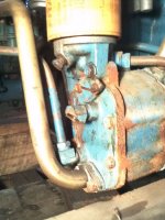
1. Gear oil cooling: The gear oil and engine oil seem to share a cooler/heat exchanger:

trans cooler.jpegoil cooler.jpeg

The gear end is currently detached. For the velvet drive gears, I know which side is the outlet and which is the return... but I do not know which is which on this cooler (or are they interchangeable?). Or do I have this all completely wrong...

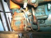
2. Oil pan hose: This hose is fed by a fitting at the bottom of the oil pan.

oil pan.jpeg

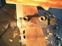
Does it maybe tie into some external oil cooler? I am thinking maybe, since this...

ext cooler.jpeg

was found loose with the engines (just this one). Thing is, there is no fitting of any kind that I can find where the loop would connect back to the engine. I am guessing this hose would be a return, but then where is the supply? (or is it a supply but where is the return?) Forgive the rookie questions, but marine stuff is all new to me!

I will need to ask question number 3 in another post because I am maxing out the image limit!
 
And for those still following this marathon thread (hopefully you are still with me Rick!)...

Question number three...

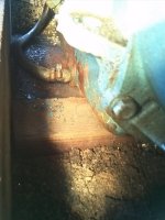
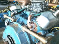
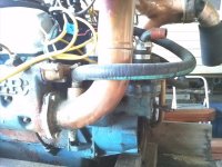
3. Exhaust Risers: These engines came with these funky hand-made copper exhausts, as well as lots of custom fittings throughout the engine cooling system. I am guessing the originals were badly corroded and original parts were not available. It is a very simple raw-water system:

front.jpegraw out.jpeg

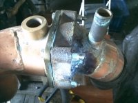
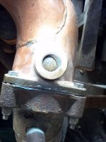
What is puzzling me is the extra fittings on the risers:

elbow.jpegjacket.jpegflange.jpeg

The tube fitting is open to the inside of the elbow. The threaded fitting opens to some kind of double-walled jacket, but from everything I can see, the jacket looks like a dead end...(??????) Also, these extra pipes you see...

pipes.jpeg

were included and seem to be the exact size and shape to have the one fitting feed the other. But what use would this possibly be? When I first saw it I assumed this was for cooling the risers, but there is nothing in the system which would feed these things. The raw water return from the engine hits the exhaust right behind the manifold, so these don't seem to have anything to do with that. What am I missing here?

Thanks to all who have offered advice! I may have brought home the weirdest pair of marine engines ever, but I am having fun trying to figure them out!

Jon
 
And for those still following this marathon thread (hopefully you are still with me Rick!)...
Yep..... still here!


I may have brought home the weirdest pair of marine engines ever, but I am having fun trying to figure them out!
Jon, I think that your last sentence is an understatement :D, and that you have the cart way ahead of the horse here! :D
These Chrysler engines are very likely from an entirely different set up. The copper exhaust system is likely custom made for that application only.
IMO, you need to first learn just what engine/transmission configuration your hull and prop shafts are set up for.

What I'm saying is; begin with what your hull requires..... NOT with how these Chrysler engines are currently configured. I think that you're working in reverse here.
Since this hull came to you minus engines/transmissions, you'll need to find a similar boat to look at.

******************************************

Although they used nice bronze parts......, these are threaded pipe fittings being used for sea water plumbing. I don't care for this, as they be internally restrictive at each male/female thread transition.


This shows copper pipe fittings that are certainly less restrictive at the interior.

View attachment 5947


This sea water introduction port (below) is rather goofy to me... unless this is what you're calling "double wall".

I say Goofy in that there is no "riser" here in terms of height. Any sea water entering the exhaust flow is right at the end of the main exhaust manifold. This would easily lend itself to what's called "water reversion", given the right rpm, intake/exhaust valve over-lap, etc. But again....... this may be double wall, in which case it may be OK!


Today's exhaust manifold "Risers" or "Elbows" introduce the sea water at the down side at the elbow bend.
Add to this...... the above is very old and outdated technology, IMO.

BTW, the hose attached to the oil pan may be a remote drain hose.
If it's capped offed or plugged at the other end, I'll bet that's what it is.


.
 
I hear what you are saying Rick. I think Dan was making a similar point. But as long as I am staring at these things, I figure I will try to get them running and see what happens from there. I am looking at it as a low-risk learning opportunity, mostly. Besides, part of me kinda likes all this goofy antique homemade stuff... it is like trying to solve a puzzle (with a few pieces missing in this case!).

I think you are right about the oil drain hose. Can't believe I didn't think of that but like I said... Rookie!

Thanks for lots of good advice.

Jon
 
.............. Besides, part of me kinda likes all this goofy antique homemade stuff... it is like trying to solve a puzzle (with a few pieces missing in this case!).
Jon, understood.
You may like or enjoy tinkering with this NOW.... but wait until you're out on the water and have an issue or two! :mad:

I don't disagree with the tinkering at all. I too would get them running and take cylinder pressure readings, etc.


.
 
The 361 is a wedge chamber. The HD heads have a smaller chamber than the late 60's early 70's wedge heads. The hd heads have small valves but huge valve stems to shed heat, and the exhaust had some that were sodium cooled. The 413 street engines use the piston on the right with a closed chamber head that had 10.1:1 aprox compression and had a great squish and quench area. I have this version of the 426 wedge in one of my boats that has only .045 between the piston and head at TDC. I run it on 87 octane with 10% Ethanol and it runs without pinging at all. I tired the same engine with the open chamber heads and it pings so bad on Ethanol you cannot even get it to plane. This proves the squish and quench really works with wedge engines. I am not sure what the effects are on small Chev engines. I will be out on the Inter coastal tomorrow boating and consuming refreshments!
I am looking for another aluminum 440 bell housing if you know anyone who may have one. I have several cast iron ones here but need another aluminum for a 510 ci, 500 HP engine I am finishing up in the spring that needs to be very light. Any leads appreciated.
Dan
 
Back
Top