Logo

Twin Chrysler 383 mystery engines... Any info?

tollyjon

New member
cleardot.gif

I recently purchased a pair of Chrysler Marine 383 engines (see pic) to re-power my 32' tollycraft. I know a little bit about engines but this is my first experience with marine inboards. I was told they were 383's and that they had been re-built, with about 300 hours since the re-build. They have been sitting on pallets for years. Nothing was documented but they spin and look good, and the price made it worth a gamble.

Here is the problem: the I.d. tags are nowhere to be found, the casting numbers on the block don't look like anything I am finding on line, and I have only found a few references to Chrysler even making a marine 383 (assuming that is what I have here).

They are very strange beasts... They appear to be raw-water cooled? They have a very unusual custom-made copper exhaust system. The distributors are on the rear (transmission) end of the engine and the flywheel is in the front! The exhaust manifolds appear to have dates as part of the casting numbers, but they don't make sense as one ends in -70, the other in -59!

Casting numbers I can find:

Block: 1945429-6 L.S.
Exhaust manifolds: SCC E6219M (then 11-30-70 and 10-26-59 respectively)
Intake manifold: 2205968 4 (11-12 and 12-20 on seperate plates)
Flywheel housing: E6274M
Engine rear cover: E-5731-M G


Help!!! Does anyone out there have Chrysler 383's or know anything about them? Anyone know how to ID these things? Is the model/serial number stamped somewhere other than the (missing) tags? Any help would be greatly appreciated! I have scoured the web and found virtually nothing...

Thanks!!!

(I have found lots of good info here in the past, but this is my first time posting!)
 

Attachments

  • twin chrysler 383 v8s.jpeg
    twin chrysler 383 v8s.jpeg
    71.6 KB · Views: 32,322
I'm not a Chrysler Marine guy by any means. Hopefully, the Chrysler experts here will chime in here, and will tell you how to determine what these actually are.


I believe that these are set up for a similar old style ChrisCraft Flywheel Forward installation.
One of them is likely a Reverse RH rotation engine.... the other is likely a Standard LH rotation engine (as viewed from the flywheel end).


As for the engine orientation, the front of the engine is still the front of the engine, and the rear (flywheel end) is still the rear.
It's the installation orientation that is quite different from what we're used to seeing.

So basically, your distributors are at the front of the engine.
Your flywheel is a the rear......, just like all 383's, 318's, 360's, 440's, Fords, GM's, etc.
DSCF7557_cutout.png


BTW, the Chrysler Marine Intake manifold 2205968 4 comes up as a 440 manifold.

2899909.jpg


.
 
Last edited:
Thanks Ricardo!

I am also in Portland, btw. I was starting to wonder if this wasn't, as you say, the whole engine mounted backwards with the transmission bolted to the "front." If that is the case, then I guess all the internal parts and the firing order etc. are set up with the "front" of the engine being the transmission end. Very good thing to know!

If you think this setup is from a Chris-Craft, I wonder if I should post the question over in the Chris-Craft forum...

As for the intake manifolds, I am curious where you found the number. Is there something on line or do you have a book? I wonder if the 383 used the same manifold as the 440, or if I am actually looking at 440s?... The guy I bought them from didn't seem to know a heck of a lot about them... maybe he had it wrong. My intake manifold is the "bridge" type (probably not the right term), meaning it spans from one head to the other without attaching to the block (block has a sheetmetal cover under the manifold. That seems to be an unusual setup, based on pictures I have seen of other engines... might help solve the mystery!

Thanks for your help!
 
Well, I mentioned Chris Craft because they did this goofy flywheel forward installation for several years. It may not be only Chris Craft either.

I'd check with both the Chrysler guys and Chris Craft guys here.... they know a whole lot more about this than I do.


As for the intake, I just did a quick Google search, and that's what came up tagged to the image and that p/n.
That same source also says; The 2205968 intake was used on 4 barrel 361 and 383 "B" engines from 1962 through 1966
Like said.... the Chrysler guys here can set you straight on this.

As for the engine internal components, again.... if one is a Reverse RH rotation, certain internal components and assembly procedures will be different.
Camshaft profile, wrist pin offset, main seals, etc.


Does your boat require a flywheel forward installation...... or is your installation more conventional?


.
 
Thanks guys, VERY helpful. Looks like I have 361's!

Ricardo, regarding the flywheel-forward setup: My boat came originally equipped (in 1964) with Gray Marine 350's and (I am told) velvet drives. I am assuming this was a conventional rear flywheel setup. These front-flywheel engines seem like they will fit... mounting pattern etc is very close... they came with velvet drive gears (2.57:1 reduction). Other than looking rather odd, I am not sure what the functional difference is with the front flywheel setup and the standard setup.

I have done some more poking around on the web and found pictures of lots of older Chris-Craft engines (1940s-1950s) with this same front-flywheel arrangement. Now I am wondering why they chose to do this? I am still hoping I can use these in my boat, but maybe I am missing something.
 
I am not sure what the functional difference is with the front flywheel setup and the standard setup.

I am still hoping I can use these in my boat, but maybe I am missing something.

I may not be following you..... I don't know if you are missing anything.... but I think that we are missing some information from you.


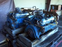
  • Are your engines now Flywheel Facing Forward with Front Crankshaft drives aiming towards the stern....., like shown with the 383 photo????
  • Or, are they Flywheel Facing Forward with Flywheel end V-Drive transmissions????
  • Or, are your engines now Flywheel Facing the Stern, with Flywheel end transmissions????

Which ever the case, there will be critical engine/shaft alignment, but I suppose no different from any other re-power.
There are quite a few I/B guys here that can explain the procedure to you.

**********
My boat came originally equipped (in 1964) with Gray Marine 350's and (I am told) velvet drives. I am assuming this was a conventional rear flywheel setup. These front-flywheel engines seem like they will fit... mounting pattern etc is very close... they came with velvet drive gears (2.57:1 reduction).
Other than looking rather odd,
I don't believe that these Chrysler 383's are considered to be "front flywheel" engines. I think that you'll find that these are "Flywheel Facing Forward <slash> front crankshaft drive" engines, or what some call the Goofy Chris Craft installation.

I believe that they chose the FFF/Front Crank drive in order to keep the prop shafts low without exaggerating the prop shaft angle. With the Flywheel towards the stern, the large flywheel diameter prevents the center line of crankshaft from being low in the hull.
When the engine was flipped around, now the center line of the crankshaft is closer to the hull.
Here's an old SBC 327Q installation....... it looks like it's sitting in the engine bay conventionally, but it is NOT.

The 327Q is a SBC. The ignition distributor is at the rear of the engine, even though this end faces the Bow of the boat.
The transmission is being driven by the front engine crankshaft, even though this end now faces the Stern of the boat.
I told ya........, Goofy, isn't it???

Something like this Walters V-drive..........

boats-v-drive-propulsion-systems-25455-377349.jpg


..... or this B/W V-drive may have solved the problem..... but I'm not sure what year drives like these become available.

velvetdrive71c72cvdrive.jpg


In terms of being conventional, I'd say Industry Standard would be Flywheel AFT, like in this simple illustration, or in this stern drive illustration......... or Forward Facing Flywheel engines w/ V-Drives like in this simple illustration.

These Chrysler 383's are not set up for any of the above installations, because they are driving the transmissions from the front crankshaft area... not the Flywheel Ends.

Oddly enough, a conventional Flywheel End transmission drive for a Starboard RH Reverse engine, may become a Port RH Reverse engine with non-reversing V-Drive transmission.
Both rear of engines would still be the flywheel ends.... they just simply face towards the bow, instead of the stern.

NOTE: this changes nothing to the means of determining engine rotation or front/rear of engine.
Front is front/rear is rear just like if these were car or truck engines.
You will need to determine the rotation of your existing engines in order to know if these Chrysler engines will work for you.

*******************

Here's a conventional shaft drive installation (below)..... flywheels are facing the stern where the transmissions drive the prop shafts.
(those Chrysler 383 installations would have been opposite of this)

Look at the notation regarding rotation and the circle/arrows.
Although correct, this is not the industry standard means of determining rotation.
Standard means would be as though viewed from the flywheel end ......... such as this Standard LH rotation engine........ or this Reverse RH rotation engine.

Top of image = front of engine.
Bottom of image = flywheel end.
The circle arrows are somewhat misleading unless we read the print carefully.

attachment.php


*************************

Here's another that can be confusing (below).
This should actually read; "always view engines from the flywheel end" to clarify the Forward Facing Flywheel/Front Crankshaft drive engines (the Goofy ChrisCraft)...... otherwise this notation would be correct.

engine-rotation.gif


Sorry to get so far off into rotation, but sooner or later you'll need to determine this.


.
 
I am following you Rick, and yes I did omit some critical information: The engines were removed from my boat long before I got my hands on it. I am looking at a bare engine compartment speculating about what the exact setup might have looked like. The Tollycraft owners manual from 1964 specifies Graymarine 350s but has zero information beyond that.

As for the gears, they were definitely not v-drives.. I have been told (but have not verified) that they had velvet drive gears. If that is the case, i think they must have been 71c with 1:1 ratio, because (from what I can gather) that is the only model which has a 4" flange on the drive end (my prop shaft has a 4" flange). Also, I don't think there is enough room, lengthwise, for reduction gears - these chryslers will just fit (I think) with the 10.5" length of a 1:1 model. The 17"+ length of the reduction gears would put the forward end of the engine past the forward wall of the engine compartment. Hopefully 1:1 gears will be ok here... I am not hugely concerned about power or performance... I will probably be potting around at 1/4 throttle most of the time and certainly not pulling skiers!

Luckily for me all the linkage, cables, wires, props, shafts etc are all there and appear to be in excellent condition. I think the boat was fully operational at the time the engines were taken out. My guess is they were pulled for a rebuild and the owner ran out of money or interest or some such thing.

As far as these goofy engines go, I can see what you are saying about the transmissions being bolted to the front of the engine, and it is indeed goofy. The transmissions are detached currently, and I can look right through the bell housing into the oil pan!

It seems the orientation is not the only thing that is goofy here... The block casting numbers match up with a 361ci, made in 1965. I have combed through about 2/3 of the threads in the Chrysler inboard forum and cannot find a single reference to a Chrysler marine 361. Nothing on the web at large either. I seem to have a knack for finding oddball stuff without really trying!

As far as determining the direction of rotation, I am kind of at a loss... May just bump the starters and see which way they move... Unless you think this is a bad idea.

I took some very detailed measurements from the engines this morning. Now I am heading up to the boat to really scope things out and hopefully convince myself that these will fit without an epic struggle. Goofy or not, if they run and I can get them to fit I will probably use them!

Thanks for all your insights!

Jon
 
HI
I have torn down many of these. I need more pictures but what you have is the HD truck version of either the 361 or 413. These were the only 2 engines manufactured with the 3 bolt holes in the middle of the head, all other versions of the big blocks were only 2 bolt holes in the middle. The exhaust valves are sodium cooled, there are hardened seats in the exhaust side from the factory, they have huge replaceable valve guides. Rings are chromium, crankshaft is forged Kellog steel, some of these ran timing gears and not chains. Some marine versions ran a timing chain on one engine and timing gears on the other. You can run these engines wide open throttle for several years and they will not over heat or come apart. They weigh a lot more than a normal big block. They were very commonly found in 5 ton trucks, buses, transporters and motor homes. Take a few pictures of the front harmonic balancer for me and measure the diameter of it. Although heavy these are crazy strong engines.
Hope it helps
Dan
 
P.S. to Rick, I took your diagram and ran through the wires today. No big surprise at this point, the results were.... Goofy. Clockwise around the distributor: 18724635 on one and 18724563 on the other. Some of those wires might be scrambled, but the two are close enough, maybe this is some oddball firing order? Also, #1 was about 180 degrees different from one engine to the other. Kinda suggests same rotation for both...?
 
Jon, if you can't turn the engine over with the starter motors, there is another way to determine rotation, but by hand.
Bring #1 cylinder to TDC C/S. This must be TDC Compression Stroke.
Take a look at the distributor rotor position. It should be lined up with #1 spark plug wire cap tower.

Roll the engine over a bit so that the distributor shaft rotates in the conventional direction (they'll both rotate the same way due to the oil pump).
See which cylinder is scheduled to fire next.

The 383 firing order and distributor rotation are shown here.
0900c152800527b4.jpg


If the next cylinder scheduled to fire is #8, (Standard LH rotation firing order), then that's your Standard LH engine.
If the next cylinder scheduled to fire is #2, (opposite for RH firing order), there ya go..... that's your Rev RH rotation engine.

Do same to the other engine.

Dan, I guess if these could be 361's or 413's, that would explain why Jon's Chrysler Marine Intake manifold p/n 2205968 4 comes up as; 2205968 intake was used on 4 barrel 361 and 383 "B" engines from 1962 through 1966
Here's my source for that.


This is interesting. Looks like some commonality here with the image at the right side.
Is this 383 the same 383 that shows up in the Road Runners of the late 60's. Like said, I'm not Chrysler historian at all.
rota.jpg


As for the front harmonic balancer, this will have been changed considerably. There will be a special fixture that has replaced the balancer, correct?
The Rear "Flywheel End" now drives the sea water pump and alternator.
The Front "Crankshaft End" now drives the transmission.


So.... apparently the mystery continues!


.
 
Last edited:
Thanks Rick. I will try that out tomorrow, and post some more pics. Did you see my earlier post about the gears etc? Update on that post: re-checked the 1964 owner's manual today... it does, in fact, say that the the boat had borg-warner gears (ratio not specified), and gray marine 220hp engines (AMC 327's I believe) not 350s as I said in that post. Will see what I can find out tomorrow.
 
P.S. to Rick, I took your diagram and ran through the wires today. No big surprise at this point, the results were.... Goofy. Clockwise around the distributor: 18724635 on one and 18724563 on the other. Some of those wires might be scrambled, but the two are close enough, maybe this is some oddball firing order? Also, #1 was about 180 degrees different from one engine to the other. Kinda suggests same rotation for both...?
Jon, since the crankshafts are typically the same between a Standard LH and a Rev RH engine, the firing order simply becomes reversed.
The 383 that I'm more familiar with, the LH engine firing order is: 1, 8, 4, 3, 6, 5, 7, ending with #2
The Rev RH engine firing order would be: 1, 2, 7, 5, 6, 3, 4, ending with # 8..... or in other words, just opposite but begining with #1 cylinder.

I'm not sure what 18724635 on one and 18724563 on the other would represent.
Notice that they both begin #1 (of which is normal) but also notice that #1 is followed by #8 on each engine.


.
 
Hi
Measure the length of the hold down bracket for the intake manifold valley pan and tell me what it is. There are 3, 1/4" bolts holding it down, one bracket on the front and one on the rear. I will then tell you what motor you have. The 361 id shorter than the 413. I just tore down a 413 like this a few months ago. It was like new inside. The heads are barely broken in, it was used on Natural gas. The heads have the water return in them as this was used to separate the head cooling from the block cooling. This is the HD and industrial version of the engine. The only plant that built these was in Marysville Michigan. Cool note, the inside of the block is signed by the fellow who fit the bearings as each was hand built. These were built on the same line as the famous 426 HEMI engines.
Dan
 
Dan, I see that this thread has sparked an interest with you..... and that's what's needed here. Wish that I could be of more help.
You have quite a bit of knowledge on these........ you must be one of us "Old Guys!" :D :D

Dan........ Questions:

If these are 361's, what is the firing order for a Standard LH rotation engine?

Are there alternate firing orders (with camshaft change) for this engine?
(I'm trying to understand the two firing orders that Jon came up with. These don't make sense to me: 18724635 on one and 18724563 on the other)

What does this mean..... and where are these located?
"only 2 engines manufactured with the 3 bolt holes in the middle of the head, all other versions of the big blocks were only 2 bolt holes in the middle."


Lastly, you mention Big Blocks when discussing the above. Are these 361's in the BB family?

.
 
Last edited:
Yes they are big blocks. These were fitted with the HD heads. Look at the exhaust manifolds, there are 3 bolts holding the manifold to the head in the middle, all other heads only have 2. The flange for the exhaust manifolds to the head is protruding, all other heads this is flush and set back. The heads from any 383, 400, 413, 426W, 440 will bolt onto these blocks to save about 200 Lbs of weight. These engines are also only about 7.5 compression ratio, little low on power but did not detonate under extreme loads.
Firing order is same as any big block 18436572 for std rotation.
Once I have the hold down distance I will tell you exactly what it is. If you remove the fuel pump and look inside, see if this engine has a timing chain or the drive gears. Some were built with special cams and drive gears instead of chains for reliability.
Built my first big block in 1970, it was a 440 six pac in a 70 Challenger RT
Never went back from that day.
Hope it helps
Dan
 
Dan...... yes, that certainly does help. You are a wealth of knowledge on this, unless you are BS'ing us! :D :D :D Of which I wouldn't know! :D
Just kidding you!

Yes, 7.5:1 C/R is certainly on the weak side for Marine power..... especially at only 361 cu in per engine in a 32' tollycraft.

Another few questions since we're holding you captive here:

Are these considered to be "Wedge Head" engines?
If so, do these guys who mess with them play around with a quench effect style combustion chamber/piston design?
(the Chrysler Wedge Head guys know all about the Q/E with these engines)

*********************
We still don't know if Jon's installation requires Flywheel Facing Forward/Front crank drive, or Flywheel Facing AFT/Flywheel end drive.

Jon, that's your homework assignment for the weekend! :D

See if the parts that came with the boat include Borg Warner pattern flywheel covers.
If you see B/W F/C's, then this suggests Flywheel Facing AFT/Flywheel end drive.... unless V-drives..... and you haven't mentioned V-drives.

Pictures, pictures, pictures!


.
 
Last edited:
Dan, here are some photos:

Timing gears.JPGEngines Rear.JPGLH Balancer 1.JPGRH Balancer 1.JPGRockers.JPG

I couldn't resist the urge any longer... put the jumper cables on them today. They are indeed a LH/RH pair. Both distributors spin counter-clockwise, viewed from above. If the current placement of the wires has any meaning at all, that gives a firing order as follows:

LH: 15364278

RH: 13654278

(also, #1 is rotated about 180 degrees from one alternator to the other)

Not sure what to make of this...

I also attached a view of the non-flywheel end of the engines. Raw-water pump, oil pump, fuel pump and distributor are all on this end. I am assuming there were alternators on the flywheel end.
 
Woops, just noticed those last couple posts. You guys are great. Heading back to thhe motors now for more measurements! More soon!
 
valley pan bracket.jpegengine comp left.jpegengine comp right.jpeg

Dan, I measured that valley-pan bracket (now I know what that thing is called!). It measures 7-1/4" both front and back. I took a photo just to be sure (bracket is in the center). I think a pic in my post from earlier today shows the timing gears you were mentioning. They look to be the same in both engines.

Rick, just to reiterate, as some of my earlier posts may have gotten lost in the shuffle... The block casting number did ID it as a 461, built in 1965 (thanks Daves69). My boat came to me with no engines or transmissions, hence the vague answer when you asked what the setup is... definitely no v-drives. I have attached pics of the starboard engine compartment as it is. I'm guessing it was a standard rear-flywheel setup. The 1964 owners manual says it came with 220hp Gray Marine engines and Borg-Warner gears, but says nothing beyond that.

Thanks again! If it weren't for you guys I would be standing around poking these things with a stick!
 
Here is the final lowdown based on your dimensions and pics. You have the first head generation version of the 361 HD engine. Notice in the rocker picture the hold downs for the shafts are aluminum and not the 1964 and later version that are cast in the head. The version you have was found to be less reliable than the cast in version, call it evolution. Also the first generation used the 4 bolt hole covers, later they were 6. I think that head was used 1 year only. The valley pan hold down picture shows it is a 361. The only engines to use those heads are the 413 and the 361. In their day the 361 was well know for reliability and torque, not horsepower. In fact it was rated at 186 HP in its best form. It has about 7.5 compression, which when we had gasoline was fine, with today’s low octane Ethanol do not expect to get much more than about 170 HP out of it. I have attached pictures of new standard engine pistons and HD engine pistons for it showing the massive dish that was used to lower the compression. Yes I did just go into my shop and pick them off the shelf. I have a complete machine shop for these engines that has never seen anything but Chryslers, 99% big blocks and 1% small blocks. No Chebby’s allowed in there.​
The bad thing about your engines is the low power to weight ratio. In order to make them worth using you need to remove all that old heavy iron down to the long blocks and build them back up with rear bell housings and updated parts. Bad thing is there are no light weight manifolds. I have made some great adapters for the standard heads to use new light weight aluminum manifolds from the 5.7 Mercruiser engines, but not for these old rare HD engines.​
All in all my advice is not to use them. Chrysler over the years advanced greatly with their engine designs. If you look at the 1995 and newer 360 Roller magnums that have the new head design, roller cams and lifters, better valve geometry etc, they give 3 times the power to weight ratio over those 361’s. A low mileage pick up engine is around $400 or so from a recycle yard. Remove the fuel injection and put on an aluminum air gap manifold and 600 CFM Edelbrock marine carb. Remove the distributor and gat a new electronic one from procompelectronics.com for less than $100. Put on an updated aluminum bell housing with the new high speed starter. A light weight set of HGE aluminum manifolds from Peter at manifoldwarehouse.com (tell him I sent you), I have used the 5.7 Mercruiser ones on small blocks as well. Use the Hurth aluminum transmissions, used everywhere and closed cooling system and you will have a dynamite power package that is light weight, update, and parts available and very reliable. Those roller magnums go 400,000 in trucks, My wife’s just hit 300,000 and does not leak or burn a drop of oil.​
The big blocks are great power plants but only due to huge cubic inches and only when lighten up with new aluminum parts. You have heavy big blocks with the smallest cubic inches and massive iron parts. If you put them in you will be disappointed. Hate to be the bearer of bad news but better now that later.​
Well now you know exactly what you have.​
I am off to pack my truck as I am heading to Florida for the winter. I have 3 boats there and hear them calling me.​
Keep salty, wet, full of rum and never miss a full moon over the water.​
Dan

Valley pan hold down bars B vs RB.jpgpiston side view HD vs Std.jpgpiston top view HD vs Std.jpg
 
Dan, great info, once again.

Jon, the drive coupler that I mentioned earily was regarding Borg Warner. What you show here, is the front crankshaft drive.
Borg Warner looks like this and would attach to the flywheel for a flywheel end transmission.
18-5661_0.jpg

ALTDA-106A.jpg
 
Dan, thanks a bunch. You have given me a lot to chew on there! Your knowledge of these engines is truly impressive. If nothing else, these engines will be a low-risk learning aid. I am a rookie with marine stuff so I am bound to screw up some things! If I can get them running without too much effort I may just drop them in and use/abuse them while looking (read: saving $ for!) the perfect engines. Glad to hear you are heading for Florida (ok maybe I am just a wee bit jealous!). And since you mentioned the full moon over the water, here is how it looks out here in Portland... Happy travels!sunset.jpeg

Rick, I will surely keep pestering you for advice, though I guess I should start a new thread since Dan has definitively solved the "mystery."
 
Yes, mystery solved!

Rick, I will surely keep pestering you for advice, though I guess I should start a new thread since Dan has definitively solved the "mystery."

Well, I'm honored to hear that compliment....., but I'm not your Chrysler guy. I'll sure help where I can.
I think that Dan has proven to be your Guru on this.... he's very knowledgeable on these.

I will say that when alignment time comes, that's when some real technical work will begin.

Jon and Dan..... I'm still curious as to the firing order.
If the Std LH rotation engine firing order is 1, 5, 3, 6, 4, 2, 7, 8..... then why isn't the Rev RH firing order 1, 8, 7, 2, 4, 6, 3, 5 ?

.
 
Oh yes, the firing order... One mystery still remains! I may just pull the valve covers and turn the engines by hand while watching the rockers... Or something like that. A bit tedious, but it should provide the answer. My guess is they have the usual order, and someone just pulled the wires at some point and screwed up the re-install.
 
Thought I would answer this before I pull out in the morning. My Chrysler marine book shows the 361 the same as all big blocks.
RH 12756348
LH 18436572
The gear drive does not change anything as the cam is designed to give the same rotation and firing order, just turning the opposite way. I have a few of those cams somewhere.
My guess is someone botched up the wires. This is common if a ford guy wires it as their numbering is different per bank. You then end up with fire out the top!
Let us know how it all turns out.
Dan
 
1... My Chrysler marine book shows the 361 the same as all big blocks.
RH 12756348
LH 18436572

2... The gear drive does not change anything as the cam is designed to give the same rotation and firing order, just turning the opposite way.
1... That's what I was thinking. Thanks for confirming.

2... Yep... RH Reverse engines with two gear cam drive, the camshaft direction remains Standard.
If chain and sprocket drive, or two gear w/ idler gears (four total), camshaft rotates with crankshaft rotation.

Now, if both RH and LH engines use two gear drive, then the camshaft would rotate opposite crankshaft.
In either event, it's all made correct for the oil pump and distributor rotation via the cam drive gear, and the distributor driven gear helical cut.


Dan, I don't know if Chrysler used the four gear cam drive or not (1 drive, 1 driven, two idler gears).

Dan, perhaps you can explain these gears to me.
Obviously the spring dampened drive unit is centered on the crankshaft. That would be the transmission drive.

The large gear at 12:00 O'clock position would appear to be the camshaft "driven" gear.
I don't see two idler gears here, so I'm assuming that this is a two gear camshaft drive.... yes/no?
I'll also assume that the camshaft "drive" gear is hidden behind the transmission coupler.

What is the small helical cut gear at 12:00 O'clock also?

What is the medium diameter gear at the 10:00 O'clock position?


.
 
Last edited:
Dan, a few one more questions/comments.

I asked earlier if the 361 engine cylinder head had a wedge shaped area in the combustion chamer..... (I.E., a D shaped flat surface area off to the side of the main chamber).
I'm not familiar with this engine, but am somewhat familiar with combustion chamber design.

If the piston on the left is used, and if the 361 cylinder head has a wedge incorporated, this piston would be close the equivilent of a Full Dished SBC piston, of which is not desireable for a more true SBC Marine Engine.
The piston to the right could offer a quench or squish zone, of which is more desireable for a Marine Engine.
It would also bring that 7.5:1 C/R up.

Just curious.

 
Back
Top