Logo

BF200 burning up fuel pumps $$$$

Damn - Is that metal? If so, then I suspect that it didn't come through the filters, but likely originated in the VST or fuel pump. If that stuff was getting into the pump, no wonder they were failing. Another possibility is the fuel shut off valve - pull it and make sure it is working properly and has not broken up.

Not sure about the hole alignment and don't have my manual handy. Maybe Mike or Chris know off the top of their heads.
 
I don't think anything that big could get through the low pressure filter, so it had to be generated after that. So that means the LP fuel pump, the fuel cut off solenoid, the VST (unlikely), or the HP pump. It's important to find out which and fix it, or you may lose yet another HP pump.
 
Well the VST that is on that motor was bought used and i have put about 8 hrs on it. So, it might have have occured on another engine. I have also bought a new low pressure pump as well as a new high pressure pump. do you think the fuel cut off solenoid would generate shavings? these looked like large sand crystals, not real fine. But i can imagine that they were starving that fuel pump and caused premature wear.
 
The fuel cut off valve has what appears to be a brass plunger. It's pretty easy to inspect and test. When 12 volts are applied, the plunger should extract completely to allow fuel to flow. So look at both the plunder and the plunger seat. Having said that, I don't recall any posts on this forum that indicated problems with that plunger. But there is always a first time.
 
Well, as the teenage girls say these days....ewwwwww! The question is, did it come in with the fuel or was some of it there the whole time? The reason I say that is I've found some brand new, in the package, cast aluminum parts from Honda to have sand still trapped in them. I don't know if it is casting sand or some blasting media that didn't get cleaned out but it is definitely sand.
Since I've never worked on one of these, I can't answer your matching the holes question. Just staying tuned end for the next episode.
 
Im guessing it came in with the used part. It basically looks like a comnbination of sand/ sand blasting media and crushed ocean shells.
 
Guys I had the same scenario here and the fuel pressure regulator had failed allowing the pump to go to 100PSi this caused the releif valve (small hole in top of pump) to continually releive the pressure sending no fuel to the rail.

definitely check the fuel pressure after installing a new pump
 
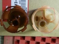
Finally I had some time to work on it. Im putting together the VST and noticed the difference between the two strainers. I've circled it in red. All the fuel pumps I have replaced have the outward indention that fits into this slot. The original strainer is the slotted one and the Ebay VST came with the strainer on the left, but had the fuel pump that has the "outward" indentation. Just wondering if you guys thinks this makes a difference.20121118_154422.jpg
 
Hey Skooter,
Im having problems getting my hp fuel pump strainer out of the housing are there any tricks to this? I have a 99model 130 that has sat for six years and I'm trying to clean and rebuild the fuel system. The fuel pump is completely locked up. When you buy the fuel pump dose it come with the new strainer ? Thanks in advance:)

catchem up!!!!
Bryan
 
I sprayed Engine tuner on the walls of the VST where the strainer is, I like Engine tuner because its very handy and has multiple uses, but you can use Wd-40 or any lubricant. Let it sit for a few minutes, then use needle nose pliers and "lift" the strainer off the walls of the VST.The strainer has three plastic "clips" that go into the notches of the walls of the VST. (thats why I recommend prying and loosening the strainer berfore you pull", otherwise you might damage it. It should pull straight out, mine was stuck in there. It has an O-ring on the bottom.
 
Deer season is here, so I've put boat on back burner. I think i had multiple issues, the VST had some granular particles in that were stopping up strainer, also I had low voltage at fuel pump so i am currently replacing harness. I've alsoo replaced low pressure pump as well just for good measure. I'm hoping I have resolved this. I will keep you guys posted.
 
I have had this issue before with the High pressure pumps, the little hole is the relief port for the pump. I had the regulator fail (made the pump output pressure at 100psi)and it killed 2 pumps like this. Please replace the fuel regulator on the injector rail. This small part may save you some $$ down the track
 
UPDATE:::
Okay guys thanks for all your help...Deer season is over here in S. Texas, so now I have focused on the issue at hand...my boat....so far I have put a new fuel pressure regulator, high press pump, low pressure pump, cleaned outmy VST (found sand) in strainer, replaced fuel pump wiring harness, replaced fuel filter in VST, and all inline on engine and near boat fuel tank, I also checked all ground connections and made sure that they were clean and tight. All looks good so far..With ignition key turned to "on" position I get 12.45 volts to fuel pump, when key is in "cranking" position or rather while I am cranking engine, I get 8.8-9.0 volts while it is "under load" or cranking on a full battery charge. I know that I have mentioned this before and you guys have chimed in suggesting maybe a bad ground. So then I checked the voltage on the starboard motor (my good) motor. I am getting about the same reading as I did on the counter rotating motor. Is this normal voltage?
 
Well, it is still my opinion that, while cranking, the battery voltage should not fall below 10 volts. A properly charged and HEALTHY battery should be able to crank the engine and not go below 10.5 volts at the BATTERY terminals WHILE CRANKING. Any readings AT THE BATTERY TERMINALS below 10 volts WHILE CRANKING is a classic sign of either a weak battery or excessive starter draw.

Having said that, you indicate that you have no problems with the starboard motor and it provides the same test results.....So, I don't know if there's trouble brewing there as well or everything I've learned and been taught about 12 volt DC electrical systems is wrong.

What is the voltage at the pump after the engine has started and the alternator is charging? Also can you test the voltage... WHILE CRANKING... at the.... BATTERY TERMINALS... for BOTH outboards and report back?
 
Okay I checked voltage at battery terminals when cranking, it was 11.54 volts. So I know I am definitely having an issue, possibly ground like you guys have mentioned. But now my question is, could LOW voltage burn up my brand new pump after just 3.5 hours?
Thanks for the help, I had checked the voltage in the batteries a while back. What would be the easiest way for me to check voltage on fuel pump while running? I'd hate to "tear" into the insulated wires
 
This may sound strange, but the first thing I would do at this point is change out my battery cables. It is very possible that they are corroded inside the insulation.
 
Post #20, this thread, has info on checking voltage to the pump. Main relay was discussed.

Post #27, this thread, fuel pump overheating and low voltage was discussed.

Google VOLTAGE DROP. Many useful articles, diagrams and specifications concerning this EXCELLENT troubleshooting technique for electrical circuits. It WILL help you solve your mystery if correctly applied using an accurate DVOM.

Good luck.
 
Im thinking the "running" voltage to the fuel pump must be higher than the "cranking" voltage.I will let you know what my testing reveals. Won't have time to get to it til tomorrow. Thanks Again!
 
Yes, that is what you should see while the engine is running. That would be somewhere near charging voltage. That is good.

The only drawback about checking only voltage though, is that it doesn't tell the whole story about the health of a working circuit. A faulty circuit, such as one with a wire that has started coming apart under the insulation or where it is crimped or soldered to a connector, might show good voltage but would not be able to carry sufficient AMPERAGE. This is pretty critical in operating any circuit and especially a pump motor circuit.

If you think of a wire as your garden hose, you know that you have pressure in there but then you also have flowing water. If you have a hose that is connected to a valve with... say... 60 psi and you put the end in a bucket, the bucket will fill with water at a given rate...say 2 gallons in one minute. But, if you bend the hose and form a crimp (restriction), the amount of flow will decrease to say...1 gallon in one minute. This happens even though the pressure in the hose REMAINS at 60 psi. So, in this analogy, voltage is pressure but amperage is flow. Or, put another way, the amperage flowing in a circuit directly effects the amount of work that the circuit can do.

Not knowing how much electrical knowledge you have, I tell you all this so you can see that just because the volts read correctly on the wire, the circuit could still be malfunctioning.

This is where using the VOLTAGE DROP method of troubleshooting is very helpful. This test technique will tell you if you have any "crimps in the hose" (breaks in the wire) and where they are located.

Other methods of determining if the pump is getting enough amps would be:

to directly measure the flow in the circuit with an induction or clamp on style ammeter. Doing this requires that you have the specification for what that should be.

operating the pump with the delivery line placed in a container and directly measuring how much fuel the pump is physically moving. Again, having the proper specification helps but a general rule for in tank, automotive type pumps is between 1/2 to 1 pint in 15 seconds. This test along with measuring the ultimate or "dead head" pressure the pump can create (usually 45-60psi depending on application) will give you an "empirical" demonstration of the pump and it's operating circuit's health.
 
Okay Im not sure if I did this right, but I placed the leads on my volt meter near the relay and one at fuel pump. set it on 2000u and got a reading that fluctuated between 001 to 004..im thinking I didnt test it right???
 
I'm assuming you are trying to test for amperage per my last post??? Because, on most DVOMs, the u symbol (for micro) is only used in conjunction with measuring very small current flows. Milliamps refers to thousandths (.001 of an amp)

u or micro refers to millionths (.000001 of an amp)

Another way of saying it is:
1 amp is made up of 1,000 milliamps.
1 milliamp is made up of 1000 microamps.

In order to measure amps with a DVOM you need to move the negative lead from the "common" to the appropriate socket marked either A (for "whole" amps) or ma/ua for milli or micro amps.

If that is correct then what you are doing won't work for two reasons.

I believe that you are attempting to measure amperage by connecting your meter in PARALLEL with the circuit. DVOMs can only measure amperage in two ways; either through the use of a clamp type attachment that allows for induction measurement or by placing the meter in SERIES with the load. This requires that you physically disconnect a wire carrying power or providing ground to the pump and INSERTING the meter into the circuit so that it and it's leads carry the electrical load.

That pump may draw as much as 5 or 6 amps when working normally so using the u or micro amp "range" will yield no useful measurement even if the meter were properly attached and, possibly damage the meter. I don't know because I've never done it.

I DO NOT recommend hooking your meter in series with that circuit. Here's why:

Most DVOMs are designed and fused for measuring 10 amps MAXIMUM when measuring "whole" amps through the A socket and they are fused for 400 milliamps (less than 1/2 an amp) when using ma/ua socket.

I can honestly tell you that, on more than one occasion, I have seen guys hook their meter into a circuit carrying LESS than ten amps and the meter has smoked and died even while the 10 amp fuse did not blow! I did it myself one time with a Fluke brand DVOM. The fuse DID blow but the meter was damaged anyway. I was able to send it in and get it repaired under warranty but I have NEVER used a DVOM for measuring current in series since. It is just too easy to buy and use the clamp type meter or attachment if you are going to be doing this type of troubleshooting.

Also, the clamp or induction method of measuring amperage opens up a variety of testing scenarios for you like measuring how much load is really on that alternator when all the lights and the heater is running as well as how many HUNDREDS of amps your starter may be pulling off that cranking battery. VERY handy.

If you want to measure the current going through that pump, I STRONGLY recommend getting tooled up for induction type measuring.

If funds do not permit, then instead of measuring amps, measure output as outlined above by seeing what volume of fuel you can obtain from the pump in 15 seconds.

AND/OR...Voltage drop. Can't stress it enough. If you place your voltmeter leads PROPERLY in parallel with any part of the circuit that is not functioning as it should, you can read DIRECTLY from the meter how much voltage is being "stolen" from the pump. Please look/google it up and practice the technique. It serves guys like you, that aren't afraid of getting their hands dirty, a way to REALLY KNOW what the hays going on.

If you have only used a voltmeter hooked across + and -, the concept can be a little strange at first but, when you see how pretty much EACH AND EVERY connector, junction, clamp and component "robs" a small amount of voltage from the item you want to power, then you will AWAKEN to the importance of keeping all those connections CLEAN and TIGHT.
 
Back
Top