Logo

Question re Engine Mount Heights

ebacon

Contributing Member
Gentlemen,

I am hoping one of you can help.

I am repowering my boat and installing an AQ225E. I am having trouble determining when the engine is aligned up/down with the transom ring. I don't want the engine to be bound up in the transom ring end eventually crack it.

As best I can tell I need to laminate in about 3/4" thick blocks under the engine mounts but that's just by feel and looking at the exhaust coupling hoses. Is there a measurement I can take that would tell me exactly when the engine is aligned with the transom plate?

Thanks,
Ed
 
Ed, with your AQ series engine/drive, youll have a total of six flats between the transom shield and your flywheel cover.
Three flats on each..... 9:00 o'clock, 12:00 o'clock and at 3:00 o'clock positions.

These are to be triangulated to achieve the correct flywheel to transom shield alignment so that the rubber cushions will be compressed correctly by the clamping collar/ring.

You'll use the front engine mount adjustments to achieve this.
The goal..... an equal distance between each set of two flats.

You'll want to leave the clamping collar somewhat loose until this is done.
You'll also adjust these mounts as to roate the engine Port/Stbd as to align the exhaust risers to the Y-pipe.

(engine drive coupler, PDS, and out drive alignment, is all pre-determined. Once set, there is no further nor annual attention required)

Your riser to y-pipe couplers are 95mm soft wall wet exhaust hose.
I'd recommend that you replace these, and purchase this by the foot so that you can increase the length by approx 2" each.
IOW, DO NOT buy these via Volvo Penta or Sierra.
The OEM and OEM replacements are always too short, and this causes an issue that I won't go into right now.


If you'll go to the BOC Vault page, you'll see that I've put together quite a bit of AQ series info there.
I have not yet had time to this on ME.com.
 
Last edited:
Ricardo,

Thanks for your prompt reply.

I am familiar with the six tabs and used them for measurements. I got lucky! I simply wasn't confident that those tabs were for measuring since I could not find any documentation to that effect. Thanks for calming my mind.

Here are some eye candy photos of the project. The old engine was an AQ131 w/ 275 drive. The repower is an AQ225E w/ 280 drive.

IMG_1319.jpg


JobSite.jpg


OldEngine.jpg


OutWithTheOld.jpg


outdrive.jpg


TugAndWiggle.jpg


NewRing1.jpg


NewRing.jpg


TheFiveOh.jpg
 
Those pictures remind me of my own project of 6 years ago. I hope yours reaches a successful completion, same as mine did. :)

This project has been going on for a few years. I think you even e-mailed me about a year ago to check on it. It was either you or Ricardo.

I've been plugging away at it. One year I rebuilt the V8. Another year I rebuilt the 280 drive. Another year I bought the gantry crane and rebuilt it.

I was ready to do the swap this spring but quite frankly I lost confidence. My primary concerns were that the throttle and steering cables wouldn't work with the repower. I did not look forward to redoing those and kept putting the project on the back burner. I was also worried that I would find rot and have to open up a new can of worms.

Finally a few weeks ago I threw caution to the wind and went for it. So far it has actually been a lot of fun. It looks like the steering and throttle cables are compatible so that was my first relief. Then I discovered the wood was as solid and amber colored as the day the boat was built. That was serious joy!

Today I epoxied some blocks to raise the engine mounts. The 225 mounts want to sit about 3/4"-5/8" higher than the old AQ131 mounts. I could run down the height adjustment screws on the AQ225 but then they would be near their limit and taller than I would like. The wood project wasn't that bad, anyhow. I just need to give the epoxy a day to cure.

Thanks again guys for all your help and encouragement. I'm sure I will have more questions.

In fact I just thought of one. What size prop do you think I will need with this new drive? The boat is 21 ft. I have a 15x17 prop that I hope will work.
 
Looks good!

Have I given you my typical and usual NAZI warning about the PDS bearings? :D
If I have not, be sure to replace these before you install the engine and drive.
The double bearing PDS must have foward area access in order to remove it from the flywheel cover, and then to reassemble.

Be sure to pre-fill the grease cavity prior to installing the two seals. Rotate the PDS while you pre-fill.
 

Attachments

  • PDS coupler and drive shaft 2.jpg
    PDS coupler and drive shaft 2.jpg
    49.8 KB · Views: 222
hehe. Ricardo you always nudge me with details. I think the last time was about ignition timing and points. I appreciate your insight.

Good news is that the engine is in. Unfortunately I discovered that the sea water inlet pipe is out of shape and needs to be replaced. I have an spare so not too big of a deal, just a half hour setback.

What prop do you guys think I will need? The boat is 21 ft. w/ a hardtop.

Here are photos of the engine socked down and the bent pipe.

EngineIn_zps0233e087.jpg


BentWaterInlet_zps68a69d70.jpg
 
Hey, you are very welcome. It's looking good and I'll bet that you are excited to do your test run!

It looks to me that the transom shield pick up tube is correct, and that possibly the OEM suction hose has been shortened by someone. Can you re-route it and gain any length????

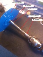
FYI: this is a chromed copper tube, and is very soft. You must be very careful when trying to remove one from a transom shield. It's very easy to bend and expand the outboard end. If at all corroded, it must be done very carefully and gently.

As for a prop, may I assume that you changed out the lower unit to the 1.61:1 ratio, and that re-shimming was done????
You'll just need to try several and obtain your WOT RPM. For this engine, I believe that WOT RPM is 4.2k to 4.6k rpm.
If you can reach that RPM during your WOT test, then you will be propped within the correct range.
You should be able to cruise at about 3.6k rpm or so.


Your riser to Y-pipe couplers are too short, as the OEM always are.:mad:
When too short, one of the double band clamps will squeeze the rubber coupler into the scalloped area of the riser outlet.
When this occurs, it will eventually restrict exhaust water flow into the exhaust system.
I'd replace both with a 95mm Marine soft wall wet exhaust hose, and of about 2" longer than the OEM length.
This will get the hose further up the riser allowing the clamps to also be further up and away from the scalloped areas.


I'd also re-route the shift cable sheathe getting it further from the steering system and giving the cable a more relaxed bend.
As the drive articulates and tilts up, the cable will travel some within the sheathe.
As you know, this is a wet cable, so the inboard-most end of the sheathe must be well above the water line.


The temp sensor and choke element wires could to be further away from the intake manifold exhaust cross-over area. This can get pretty dog gone hot here.

Lastly, what's going on with the throttle cable? Looks like it's either been melted or clamped severely in one area.
If memory serves me, the V-8 throttle cable direction will be opposite from that of the OHC 4 cylinder throttle cable operation.
IOW, the cable must now "pull" for open throttle.
Also, the barrel fitting at the end will be removed for the Q-jet throttle attachment.
 
Ricardo,

Thanks for the details. I did not think about reversing the throttle cable pull. Hopefully that can be done with my existing control box.

As for the burned throttle cable jacket, it has been like that since I bought the boat. I looks like it was laying on the AQ131 exhaust pipe at some time. Anyhow it works perfect despite being ugly. I will also replace the exhaust rubber tubes.

There are a few more things that I need to figure out. Suggestions are welcome.

1) Where to mount the remote oil filter
2) Whether to move the battery switch. With the AQ131 it was out in the open but now it is about 1" away from the port side exhaust pipe.
 
There are a few more things that I need to figure out. Suggestions are welcome.

1) Where to mount the remote oil filter
2) Whether to move the battery switch. With the AQ131 it was out in the open but now it is about 1" away from the port side exhaust pipe.

1... I'd use the standard remote oil filter configuration. You DO NOT want an inverted filter cartridge! :mad:
I can't suggest where to mount this without knowing more about your engnine bay.

2... This is a pet peeve of mine. There is absolutely no good reason to have our MBSS mounted inside of an engine bay. :mad: :mad: :mad:
Not only does this make battery management more difficult, it limits our abililty to shut down the 12 volt system in the event of an emergency.
Most boats will lend themselves to a good location whereby the MBSS is accessible from outside of the engine bay.
It may be back-mounted with the face side exposed to the inside of the cabin, or it may be recessed within an area in the cockpit.

I'd take the extra necessary measures to relocate it.
Upsize the cables to accommodate any added round trip circuit length, and you'll be OK.


.
 
Eduardo, the 18-2766 - HOSE 834751-0, and the 9-42700 - HOSE, EXHAUST 9-42700, will be Pre-Cut.
I'll guarantee you that either of these will be too short to work correctly.
Go back to post #7 and you'll see what I mean.
Why Volvo Penta and Sierra offer these in this length is beyond me. ERRRRR! :mad:

I once fired an email to Sierra and explained this.
I did not bother to contact V/P... there's just too thick of a front line to penetrate.
Never heard back from the Sierra people!


Yes, this hose in 95mm is difficult to find by the foot. All that I can suggest, is to keep trying.

Rick
 
Last edited:
Hello, Ricardo. They worked for me, I still had sufficient space to put two hose clamps on each side of the hose. Having said that, I admit that may not be the case with everybody.
 
I will keep looking for the hose by the foot.

In any event I appreciate Ricardo pointing out the potential problem. When I install the clamps I will be careful to watch out for the scallops.
 
Can anyone tell me if the factory 5.0L used a remote oil filter? Is so, where did Bayliner mount it?

Thanks!
 
Can anyone tell me if the factory 5.0L used a remote oil filter? Is so, where did Bayliner mount it?
I don't recall having seen an OEM Volvo Penta remote oil filter during these year models, most likely a dealer istalled item if so equipped.
I'd say that you could mount this (within reason) anywhere that makes sense.
I would steer clear of the inverted filter style base and would go with a base unit that holds the filter in the normal upright position.

I noticed that your fuel filter is mounted via the exhaust manifold and bolts.
 
My remote oil filter mount holds the filter in the same orientation as if it was mounted on the engine. I want to mount it to the transom but there is no room in the engine compartment. I might have to install an access panel in the rear wall of the cockpit and then mount the oil filter behind that.

My fuel filter is arrangement is a kit from Volvo Penta. I might be able to mount the oil filter in a similar manner but it would require longer hoses to reach the engine front.
 
I have good news on the stock exhaust hose couplings -- they are long enough.

One thing is for certain, there is no extra length to play with. If the hoses are just slipped on and left to rest where they want to go then there will be problems with the clamps closing out the scallops. The hoses need to be pushed about an inch further onto the riser than they want to rest at.

Thanks for alerting me to this issue.
 
The project is coming along. Everything is hooked up except the batteries and remote oil filter. I need to extend the wire that goes from the battery switch to the starter and also get longer remote fuel filter hoses.

The battery switch and remote oil filter will be accessible through this new transom hatch.

IMG_2577_1.jpg
 
I wish I could see a factory installation of this engine. I'm interested in whether they even bothered making the oil filter easily accessible.
 
I bought my 3" exhaust hose by the foot from West Marine. Their parts dept had it in stock, but then the store in Ft. Lauderdale is huge.
 
I need to extend the wire that goes from the battery switch to the starter and also get longer remote fuel filter hoses.

The battery switch and remote oil filter will be accessible through this new transom hatch.
Good call on the accessible MBSS.
Why these are installed in the engine bay is beyond me!!!! :mad:

Your round trip length will determine the cable gauge.

I wish I could see a factory installation of this engine. I'm interested in whether they even bothered making the oil filter easily accessible.
I don't think that you'll see an OEM remote oil filter installation for this engine model.
If you are making up your system, you have the oportunity to locate it where you want to.


.
 
The nights are getting below freezing and progress is slowing. It looks like testing will have to wait until spring.

Here is the finished hatch. Inside is a new panel that holds the oil filter and battery switch.

Hopefully the next two weekends will be warm enough to mount the leg, wash the boat, and button it up before snowflakes start floating around.

IMG_2583_1.jpg
 
Good news so far.

Last week I got most of the small things taken care of. Most of that involved injecting epoxy in to old holes and moving the engine compartment blower. I also charged up a battery, installed it, and turned the ignition key.

The engine briefly fired and all gauges worked. I almost fell over with relief. The outdrive lift circuit also works.

The only remaining task is to replace the U-joints on the upper drive unit. I bought a pair from marineengine.com. Now I just need to get my hands on a press. The local Volvo-Penta shop wants $500 to do the job and I just can't justify the expense.
 
Ed, you will not need a press to remove the bearing crosses once the universal shaft has been removed from the transmission bearing box and main drive gear.

Remove all of the interior C clips, and with a brass hammer gently drive on one component while enteria does the work for you.

If you have an old prop shaft spacer, these work perfectly for a tool to stop the yoke (or center section) against your bench vice anvil surface. The bearing cross caps fit nicely into this part.

In all the years that I've been working on these, I've not found one that could not removed and replaced this way.


BTW.... a Spicer 5-1306X bearing cross is a good quality replacement for these.
About $14 each if you know how/where to purchase them.

.
 
Back
Top