Logo

MEFI2 454 TBI Timing

sbarbier

New member
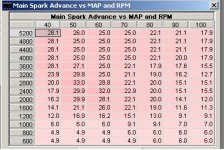
Just received a copy of Tunerpro software, bin files and definition files so I can understand how the ECM is programmed on these engines. I found some programming in the fuel and timing tables that looks kind of odd. The maximum timing advance at 100kpa is only 18* above 3200 rpm's. This plus the initial 8* is only 26*. I thought these engines should have a total advance somewhere around 30*ish plus?

I also noticed that at 3600rpm's the TA drops (I'm on my Mac so I don't have the program up in front of me right now so forgive me if the numbers aren't exact) from 20ish at 3400 to 15ish at 3600 and back to up 18 above 3600rpm. Any idea why there would be a dip in the TA curve and it not be linear?

I also noticed something I was never aware of and that is the effect the engine coolant temp has on timing and fuel delivery. The ECM will demand a longer pulse width (i.e. run way richer) when the engine is not up to temperature. This mainly serves as a choke does for carb engines to deliver more fuel until it's warmed up. Until these engines are up to 140* they will burn 9% more fuel (or more) until 160* is reached. So for those that have thermostat problems and are not getting proper temps this could be one problem for more fuel burn and possibly the reason for the fuel sheen on the water.

I'm having all these problems.
 
Your thread title threw me! :D ( how do we time Throttle Body Injection? LOL ) Got-cha...... TB Ignition!

Yep, spark lead in graph form usually omits BASE advance, so BASE must be added when looking for actual TA numbers.

The difference in a TA of 26* and 30* is 4*....... 4* could be just enough to put the engine into a range where Ignition induced Detonation could occur (not to be confused with Pre-Ignition).
There's often such a fine line between a Marine Engine's Ignition allowing for correct LPCP, and Detonation potential control.
I'd stick with the OEM TA specs and OEM associated RPM.

I can't explain why TA would "dip", as you say (cut back) and would then increase again as you describe. Interesting! Progressive Ignition spark lead (advance) is to be relative to a progressive RPM increase.
Is this being seen as you strobe.... or shown in your OEM ignition curve?


As for the ECM and lower temperature re; Fuel/Air metering (rich mixture while cold)........ makes sense. (I am no expert in this area at all!)
If you are Raw Water Cooled, and are NOT running in Salt Water, you may want to increase your thermostat's operating range. No need to run at 140* unless in Salt Water as to prevent Salt Crystallization.
160*-180* may better suit your needs if Closed System Cooled, or RWC in River/Lake water. Salt Crystallization can be nasty stuff years down the road! :mad:

.
 
I don't recall a dip in advance curve. As Rick inquired, are you talking spec or measured, that changes everything. If measured, it could be a function of current running conditions. Does this engine have a knock sensor? Any physical modds made to this engine? Also, a MEFI must have fault codes manually cleared even after a fix or the ECM will continue to ignor sensor input and run off default values. MEFI also has "Power Reduction".

The relationship between temp and injector pulse width makes perfect sense, no question it is a contributing factor in the ECM's calculation when coming up with pulse width. In newer engines, intake air temp (IAT) also plays a roll as it is a determining factor in the ECM's air density calculations.
 
Last edited:
I'd make sure you are looking at a valid tuning map for the application at hand; ie download what is in your ecu and then start to understand it vs what may be another application's tunes. 100 kPa is around atmospheric pressure so that would infer WOT operation. Other variables that must be understood are the sensors actually used on the application vs what the ECU can sense. Many of the earlier TBI units have non-EST setups so the spark map may be irrelevant. Usually an EST setup will have a knock sensor but marine engines are notorious for redefining the rules.

The dip in the timing curve is probably insurance for whoever commisioned it. Your description of the dip is under max extreme load; usually where detonation induced destruction is likely. See if the behavior is similar under modest throttle.

Yes, the temp inputs drives the fuel curve richer and that's a feature that has been around since fuel injection was ECU controlled. We used to bypass the ECT sensor on the old big blocks in the TBI'ed trucks to obtain a 'power mode'...
 
The dip in the timing is in the mapping and not measured. I believe there was other dips also below 100kpa but at different RPM's. The mapping I'm looking at is the one that was sent to me from Bob at MEFiBurn. He says it's the same one I have on my engine but I haven't been to the boat yet to download it and verify. I'll be there next weekend and will verify it's the same.

There are no mods to the engine that I'm aware of, at least nothing external.

BTW, does anyone know an easy way yo install a wideband on these engines without drilling into the riser? I would like to check the AFR to see what I'm running. I've heard from someone who has tuned these engines before Crusader has intentionally set these to run overly rich to be on the safe side.
 
Many of the earlier TBI units have non-EST setups so the spark map may be irrelevant. Usually an EST setup will have a knock sensor but marine engines are notorious for redefining the rules.
Well now I need some clarification, Mark. Must be my old gray hair! :)

The OP's thread title is MEF12 454 TBI Timing .... of which I initially thought; "Throttle Body Injection timing?????" I'm thinking to myself.... WTF!
Upon reading, I then assumed that he was referring to Merc's TB..... Thunder Bolt Ignition.... either TB IV or TB V.
If I understand, either of these are EST (electronic spark timing).... correct?

Yet now you mention; "TBI units have non-EST setups"!
So.... are we discussing TBI (as in Throttle Body Injection) or TB as in TB IV or TB V ignition systems?
To me.... there would be TBI, and there would be TB IV and/or TB V ignition.


BTW, and as a side note/question..... do any of you understand the EST module's role in ignition spark advancing?
An EST distributor's photo eye (or VR) unit is triggering only.... no actual advancing takes place within this type of distributor.
It's locked down.... and with no means of mechanical advancement.
It's all done via the Module that allows for any spark "lead" (advance) to occur.

Since we can't cause an electrical impulse to show up in the future (before actually occuring), I have reason to believe that the Ignition Module must simply offer an impluse delay (via the system's circuitry), then allow for a decrease in this delay (spark advance), as the EST system's circuitry algorithm dictates, per engine RPM (and any other data input from more complex ECM/ECU systems).
Any thoughts from you experts?
 
Last edited:
Sorry about the title throwing everyone off, just trying to define the type of engine and the issue I was seeing. It's a 1996 Crusader XLI which has Throttle Body Injection (TBI) and I was trying to determine why the timing advance in the ECM mapping has a dip at certain RPM's and not linear. It seems kind of coincidental that the dip is right about where I run the engine.
 
It seems kind of coincidental that the dip is right about where I run the engine.
You sure??? These maps (tunes) are multi-dimensional (one for each key variable) and it is real easy to 'land' on the wrong spot.

You may want to check with the source of the code to check their rationale for the non-uniform timing curve.

They are ALL setup to run on the 'rich side' - Crusader isn't the only one. The reason offered to me was that they (engine OEM) CAN"T control the hull the engine is installed in....so, look at it as though you had to foot the bill for any warranty claim - how would you set up the fuel delivery curve?

As far as the HO2S - if there was an easy, reliable way, they'd been installed a long time ago and the EPA would have mandated them. I've seen a couple and they all have very short lifetimes (I'm sure due to the cooling water).

Rick - I was figuring he was referring to a MEFI-1 or-2. Yes, those TB-IV ignited TBI units were the ones I got to cut my teeth on. Very similar to the GM setups but without the O2 sensors or the emission crap. My understanding is that the EST module works on an "average" value basis and actually 'delays' the trigger pulse vs electronically "advancing" it. I'd also bet that's why the 6-cyl modules won't work well on the 8-cyl applications.

Based on the little bit of tech data I remember reading, the EST module runs in two primary modes - stand alone and ECU controlled. In the former, the rpm determines the timing advance used - in the latter, the ECU provides a control voltage that will be modified based on sensor inputs like the knock sensor.....GM tech support used to have a bunch of very useful stuff posted on their www sites but all my links stopped working years ago.
 
Rick, I'm assuming we're talking about fuel delivery in this thread based on the title and not Merc's TB ignition since we're in the Crusader forum. I'm also assuming you're referring to the HEI EST ignition in your post where the distributor has an ignition control module in the distributor (two plugs out the side). Here's my understanding of operation: the HEI module in the distributor triggers the coil and provides the ECM with engine speed. During startup, the distributor/timing module has complete control of timing. This module has a little advance built into circuit only in case the system for any reason remains in distributor module timing mode. Once the engine is running and a predetermined rpm is reached, the ECM considers the engine running and bypasses the ignition module's timing control. The ECM is then in control of timing (ECM Control Mode) by sending the module an ignition control signal causing the module to trigger the coil. Easiest way I can explain it guys without spending too much time on voltages, module and ECM circuitry etc.

Sorry Mako, your post made it up before mine. The curve seems a little strange to me. Have been looking at a few different ones and none show a dip. Also, re O2 sensors, have you guys gotten any catalyst engines yet? I thought they had sensors in the exhaust.
 
Last edited:
sbarbier, thanks for the clarification..... guess I've not seen TBI Timing used like that before.

Thanks Mark and Woodie, I was fairly certain that some type/form of delay had to be incorporated...... otherwise, we'd need to break the laws of Physics! :D

And yes... mentioning TB Ignition while being in the Crusader Forum through me the same loop, Woodie!
 
Guys, maybe someone could clarify something for me. There is an "average" component in the timing calculation but I don't ever recall reading about the ECM delaying anything. It simply takes inputs and based on those goes to data tables to determine when to send off an ignition control signal to fire the coil. Am I missing something?
 
Woodie, I'm certainly NOT the one to comment on that.

My question was regarding a contrast between a conventional system (whereby progressive spark advance is acheived by mechanical means that controls when triggering occurs) .... to that of a system that has ZERO mechanical ability to progressively advance the spark!

I know that the laws of physics DO NOT allow for electricity to travel into the future, so how is this being acheieved?


IOW, if we trigger one cylinder with spark at 10* BTDC from a fixed Non-Advancing distributor......, how can the system's module provide that same cylinder (now at 3k rpm) with spark at 25* BTDC, if not being physically and mechanically advanced?

If we begin with "fixed triggering" (that I assume is too advanced for the engine rpm), do we delay it electronically, and then reduce the delay value as RPM increase????
Or, is this acheived by some other means????

That's what I was questioning.
You guys have the young sharp minds... not me! :D

.
 
Here is the mapping file from the ECM. As you can see the electronic timing advance has a dip in the curve which is kind of odd.

Timing curve.JPG

Like I said I'll download the tables from my ECM once I get to the boat next week to verify this is the correct one.
 
Ricardo - yes the initial timing is set mechanically. From there it is controlled by the ECM which will advance it based on the table I attached in the post above. Depending on the combination MAP and RPM it will be advanced by these numbers. There are also some other factors that play a part in these calculations as well. One of these is the engine coolant temp (ECT) which will retard the timing 2.1* above 178 deg f and slightly more above 213deg f. Another is the knock sensor which will retard the timing 9.8* if a knock is detected.
 
Rick:

For EST "how it is done", check here: http://www.megamanual.com/ms2/GM_7pinHEI.htm

It has the best description (that I've found) of how the EST (HEI) is 'advanced'...some call it "next cylinder" but I was taught with the 'delay' verbage.

The module takes the "applied voltage" and maps it into the 'delay' that is applied to provide a finite amount of 'ignition advance'. My earlier comment about "averaging" occuring isn't properly applied to the EST operation but it is relevant to electronic 'advance' timing light circuitry - sorry but the old memory circuits produce random errors occasionally.

sbarbier - I'd suspect the timing map you have is for a newer engine (8.1 or similar) based, primarily, on the WOT shown in the table. As the timing change at 3200 rpm is controlled by MAP, I'd suspect it was "empirically derived" for a specific engine, with a torque peak around 3200 rpm. You may get a more authoritative response, faster, from one of the board that support marine aps of the tunerpro s/w...
 
Glad to help - those guys have a neat product and a ton of information. I know a few that use the MegaSquirt for some serious racing and they haven't found anything that board couldn't do. If I had to migrate to injection, it'd be on the top of the list. (Yes, I hate proprietary products.)
 
Back
Top