Logo

What did I do wrong

joel8080

Contributing Member
I just did some electrical work on my 89 Blackfin (some wires &new a fuse box) and now when I start the port engine it shows a charge on the amp meter, the one at the control panel, but when I start the starboard engine it shows negative at both Port & Starboard amp meters.

I have 2 different engine switches they are on/off on each.

What did I do wrong

Joel8080
 
Last edited:
Draft up a schematic, and post it.
That is the only way that any of us will understand and actually see what you've done, IMO.

Question: Are these actual Amp Meters, or Voltage Meters?
 
There Voltage meters, The wiring I did was from the New Blue Sea fuse box to the GPS, Stereo, Fishfinder 2, VHF & the fuse box is wired to the + on the port Battery and the ground to the - of the battery.
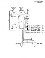
Other wise is as the boat was originally wired if you want a wireing diagram for the boat I could send one to you.

Joel
 
Again, a schematic may be much more effective.

You'll want the source for this new panel to be taken from the rear of your MBSS, not necessarily from a direct battery connection, although this is not your problem. Direct battery connections (other than battery cables) should be avoided.

Did you by chance interrupt the Positive power to the OEM hull harness or to the helm?
Did you interruupt the Negative source to the hull harnes or to the helm in any way?

.
 
Like Rick said, a schematic (especially the before and after changes) would help.

In the interim, you may want to disconnect your 'new additions' and see if the issue persists.

Since you clarified you were looking at VOLT meters, what does "is shows negative" in the original post mean?
 
Well I don't usually go off topic but I have to tell you that your message string, "What did I do wrong?", really strikes home. It is a question I often ask. The other one is "Why didn't I see that before?". Good luck on finding the problem. You are in the right forum.

Chuck Hanson
 
The work I performed was to change the old fashion tube type fuse block with a new Blue Sea ST fuse block, new ring terminal fittings and shrink tubing on the wire ends. While I did the work I disconnected the + & - cables from the battery.
Why would it show - on both engines when I only worked on the starboard engine.

Please tell me how or where to send the wiring diagram and I will send it out A/O.

Joel 8080
 
Joe, during your next post, invoke the "advanced" feature. Follow the menu for adding image files.
Or if you are hosting the image already......, just post a URL, image tag it, or make it a hyperlink.
 
Yup a pic would help us.
All that trouble just to go to another type of fuse? Dude! I wish I could have been there to try to get you to go to breakers instead. Oh well. good luck with your problem. One thing that's sorta reassuring is that both engines start. Screw the 'lectrics...go fishing!
 
Rick

I've been trying to send you a private message asking for your email and I would send you the diagrams, I guess I need some computer lessons.

Joel8080
 
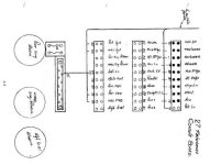
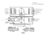
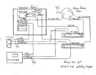
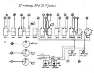
Joel, here they are.
Maybe you could point out, or explain where you think the problem is, and/or where these changes were made.
I'm usually pretty saavy at this stuff, but I'm not sure where to begin.


image 1.jpgimage 4.jpgimage 2.jpgimage 3.jpgimage 5.jpg
 
The only changes made really were to the ends of the wires with new terminal rings , I keep trying to figure out where are both the port & starboard electrical systems connected as they are 2 different systems with there own on off switch.
I don't know I keep thinking the ground but really I have no Idea where to start. How about the paralleling solenoid
 
Last edited:
Those schematics ar a bit 'thin'.

I'm thinking like DD - a missing wire or a bad connection on one end somewhere. I'd start by checking the integrity of the ground wires. I'd guess one is missing and the current is flowing thru the bonding leads and some of that may not be in the best shape.

Joel - exactly where in the schematics is the 'new fuse box'? All I saw were the dash fuses and the combined breaker panel....
 
The fuse box was a add on by the former owner it's in the electronics box he put the old fashion auto fuse block and I changed it to a Blue Sea fuse block the only things connected are Fish finder 2, Vhf, stereo, and and 2 t top lights.

Heres a wild guess the Volt meter switch is a gauge with a on 1 off on 2 switch and one meter could it be bad I'm just guessing.

Joel
 
Let's call them "Negatives"...... (technically speaking, "ground" is an incorrect term for 12 vdc)

All Negatives can and should be common, IMO. This is likely NOT your problem, unless one Negative path has been comprimised.

Temporarily disconnect your paralleling solenoid. See what happens, if anything. Again, this is likely NOT your problem.

Suggestion: Somewhere in your OEM hull harness, you will very likely have a harness connector/connection. This will be a multi pin connector.
Your hull harness will carry both POS and NEG circuits forward.... minus what you may have added as a NEW circuit.
If the hull harness connection for Negative is breached in some way (no or weak continuity), this may be part or all of your problem.
Pull this connector apart, spray a corrosion blocker into the terminals. Plug it in.... pull it apart... repeat this several times. Not orally.... physically! Unless you have an audience! :D

.
 
Last edited:
I will be at the Boat tomorrow and try it and will let you know. any other Ideas while I'm there?. How do I check to see if one of the common paths have been compromised as the starboard engine will start & run no problem ?.

Thank You

Joel
 
Typically, in a twin engine situation with "relatively" independant systems and wiring, if one engine can cause a "reversal" of current to the other system, that screams of a bad or missing ground. MM question about what Joel means by "it shows negative" is important. Are we talking about analog (dial) guages, and "negative" means below 12 volts running, where normal charge is 13.5?
 
Typically, in a twin engine situation with "relatively" independant systems and wiring.........,
Agree to a point. But here is where we split paths:
If we are to have any Battery Bank combining ability (cranking Port from Stbd or visa-versa, for example), our engines must be Negative Inter-Connected.
This typically requires a heavy Negative cable that would join each engine.
Since our engines are our main point of Battery Bank Negative connection, from that point forward, ALL should be Negatively "common".... inluding engine and hull harnesses, providing that continuity is good.

Let me put this another way..... If we do not have this, then port/stdb battery combining and/or the use of twin engine alternator charging for a single bank, cannot exist. They must be joined, IMO.

.
 
Last edited:
When I run the port engine it reads 13.5 Volts it's a Analog gauge that is one dial with a port & starboard switch. When I run starboard engine alone or both it reads 5/6 volts.

But the funny thing is the battery is not discharged at all.

Joel
 
Joel, with what you have just described, instead of relying on the instrument volt reading, take a direct battery bank reading with a VOM.
See if the charge rate shows an increased voltage reading At The Battery Bank.
For testing puruposes, and when we want accuracy, we always want this reading to be taken directly from the bank..... not anywhere else.

But you are going to want to do the other checks that I've suggested.... hull harness, etc.
 
THis is what I put in my twin eng. boat to connect each battery, and engine NEG. together. Also, the bonding strap goes here, and the house NEG as well. There is a 8 post available. It removes the opportunity of a single loose wire affecting both engines.
2104.jpg
 
Dave, nice......, and I like the idea for smaller circuits, such as accessories or a dedicated fresh/new panel in the cabin for Nav/Radio/GPSetc., but could not bring myself to use that in the Negative return path, for any heavy cranking loads, etc.

My two engines are joined with one additional heavy Negative cable.
Each engine bank Neg makes it's own independant engine connection.
My Neg reduncy is right there in that.
(I could not recommend that two battery banks share one Neg.)

.
 
It's a 600 amp rated, about a 3/4" square cross section of copper. THose are 3/8" posts out the top. Anyway, that's far less resistance that the batteries, cables, engine block, etc. EACH battery negative goes here, and each engine block connects, there is no shared wiring. Only this block of copper is shared. Somewhere you have to trust something! It removes having to stack high current lugs on batteries or switches, something that I do not care for.
If you have an "emergency crossover switch/relay", there must be a high current path available between the batteries negative terms.
 
Last edited:
We call those "buss bars" and they are proven to be reliable for providing a common electrical path with heavy gauge wiring.

If the meter is reading 5 to 6 VDC (not less than 1V), I'd start by verifying the voltage drop that the meter indicates. If it is 'real' (only 5 to 6 VDC at the battery side of the selector switch) then you need to find the voltage drop that exists in path between the starboard engine and the panel. Verifying the alternator output is adequate, at the battery, is a next step. if that's fine, go along each 'path' (positive and negative), looking for a voltage drop in that path, back to the panel. Sometimes, you can just run you hand along a conductor/connection and find the warm spot (only works if enough current is flowing (IR Gun would be good for this, too).

The meter appears fine but the selector switch could be bad....mine goes and acts up every couple years - nothing a good cleaning won't fix.
 
Dave, understood! And I agree..... we should NOT be stacking either Neg or Pos cables on battery terminals when/if this can be avoided.
Again.... I like the buss bar idea, but if speaking strickly of engine NEG cables (ones used for heavier cranking loads), I see no reason to terminate other than directly at/on the engine itself.
(perhaps I've misunderstood how you are using this)
Each battery bank should have their own idividual NEG cable routed directly to the engine block.
Anything outside of this, adds to a potential point of failure. Again, IMOO here. Just a personal take, I suppose.
Smaller load Accessories Negs going to/from a buss bar......... Yes... fully agree! I have something very similar on my own.

The beauty is..... we all get to do what we want to on our own boats. :D


Mark, good point!
Some may not like this comment, but I've found more issues with the Perko battery switches, than with many others. I won't even buy a Perko for use on someone's boat. Dang near any other brand offers a better product...... again, IMOO here.

.
 
Last edited:
Back
Top