Logo

Murphy Power View 101

cmack

New member
Hello: I want to install a Murphy Power View to record fuel usage. I believe this unit will give gals/hour. I have J1939 engines CAN. Has anyone used this gauge and what is difficulty to install. Thanks Chuck4080
 
It is truly plug & play with the Crusader cables. The hardest part would be drilling the hole in the dash & running the wire from the engine. Find a 12v power source off the ignition switch under the dash & your done. I pulled my tachs out & put it there.
 
I want to install a Murphy Power View to record fuel usage. I believe this unit will give gals/hour. I have J1939 engines CAN. Has anyone used this gauge and what is difficulty to install. Thanks Chuck4080
Chuck, consider that gals/hour is not a means of determining true fuel economy!
Gal/mile or miles/gal is!
You will want Distance Traveled to be part of the equation, in order to have a more meaningful number, IMO.
There are systems available that read GPS speed data and input this as to give us miles/gal.
The Murphy may be one of them...... I don't know!

If the Murphy Power View will not provide this, then you simply get fuel usage!
If all you are after is fuel usage, then my above info is moot!


.
 
Last edited:
Ricks point is truly right on. So many variables dictate fuel usage. Sea conditions, tides, bottom of boat, load, etc stc. When I had ONLY a fuel useage system, I knew from 250gal down to 1 gallon. With my Garmin 4212 and its' fuel sensors, the amount of information is significantly more helful and interpretive. I do not know the costs involved with the system you propose or the area of usage you boat in but I also suggest you weigh these differences to see if you might not be better off with GPS integration.

So many websites to look at...Good Luck
 
Chuck, I see that this question was also posted on THT web site.

I made an attempt to learn a bit about the Murphy Power View as per GPS data input capable. One web site is currently down.
Any info that you can provide?


.
 
The Power View is an engine monitoring system. These units are used on all kinds of industrial gas & diesel engines. It displays all the info that is broadcast by the ECM. It will only work on newer (2007 & up) engines using J1939 CAN BUS communication standard. The unit can take the place of your entire gauge panel using only 2 wires. If you feel the need to know your intake manifold or exhaust riser temp. its there. The unit also can display fault codes & alarms. You simply can not trouble shoot these engines without knowing the fault codes. The display can be easily set up to scroll through through all the info available. One item displayed* or 4 items displayed. There is no provision for GPS input to give you MPG. You will get gallons per hour actual, gallons per hour average & total gallons used (resettable)
 
Then it's safe to assume that this is NOT NMEA data capable?

Not NMEA 0183. However NMEA 2000 devices and J1939 devices can be made to co-exist on the same network. So who knows what the future holds ? If the manufacturers resist the urge to create their own but "compatible" systems. They can say their NEMA 2000 however if you use X depth finder with Y GPS you get limited features if you don't use all one manufacturers stuff.
 
rfdlou and others: Thanks for the response and info. My engines are Volvo Penta 8.1gxil, 420hp gas. They are 2007 model and I am told they are j1939 CAN...not really sure. I was planning to get what I really wanted, miles/gal, by dividing the MPH by gal/hr. The MPH would come from my GPS.display Raymarine E80. Floscan would be better, but I am concerned about cutting fuel lines to install. rfdlou, are using the PV101 to get the fuel burn info. I have connectors that I think are used for diagnostic purposes, and I was planning to plug into one of them. my mechanic did this with a lap top and got GPH. I do appreciate your response, I hate to buy one until I know more about the unit. Thanks again for the input, Regards Chuck
 
Last edited:
I do use my Power Views for fuel consumption as fancy gas gauges and my tachs were shot. I have the "4 up" display set for gallons per hour, gallons per hour average, total gallons used & RPM. I would check with a Volvo dealer or the Volvo forum to see if any one makes cables for the hook up or knows how to make the engine connection. MurCal's web address is http://shopping.murcal.com/Welcome The Crusader twin engine hook up uses a sync cable that connects both engines together. The sync cable than connects to the cable that runs to the dash. And finally a tee connector goes to each Power View unit. Everything but the sync cable which was supplied with the twin engines, came in the kit purchased from Crusader. I think the only reason Crusader uses the sync cable is to allow you to plug in their "cruse control" system that synchronizes and sets the throttles for both engines. That thing looks like a couple of rocker switches for $600.
 
rfdlou: Well here it is 3:00am and I am sending an email. I am so excited that I have found someone that has marine knowledge and use the PV101. Further, I see your last post which answers some of my questions about hooking it up. I was told by VP consumer relations, that I need to connect to pins 13 &14. You are correct that only need to connect to two wires. Would you know how I would locate those two wires on my wiring harness. Did you wire direct or use plug connector. My engines have connecting plugs F5AB-14A66-A with eight wires which look like diagnostic plugs. For now I plan to install only one PV101 to see how it works with my engine. I am so appreciative for your information. Regards Chuck
 
The Murphy unit is like many of the "scan gauges" available for the auto applications. As noted above, it can display anything provided to/from the ECU. it behaves very similar to a "scan tool" regarding data extraction. Using connectors (vs hardwiring) is usually preferred as it maintains existing functionality (service capability and cable shielding primarily). If you understand networking interconnect requirements, it isn't hard to add the connections in a variety of ways.

For cmack - the only word of caution concerns using the ECU data for fuel consumption. My experience is that this is calculated based on rpm and injector duty cycle and not measured. This means as long as the injectors aren't malfunctioning, the data should represent reality. Using a floscan or a garmin add on, one actually measures the fuel used (vs calculating).
 
makomark: Thank you for the info. I was concerned that the fuel consumption might be calculated, but I am told it is reasonable accurate? I am just trying to find the sweet spot for more efficient running. So I guess it should give close enough data. The actual gal may not be correct but it should tell me that I am at the most efficient fuel burn, what ever it is. I just hate cutting fuel lines for the floscan unit and I am told that engine when running hot could vapor lock (per marine dealer). This has been a tough decision for me, my electronic mechanic is concerned about installing the pv101 because he is not sure where to install it on the harness ...he is afraid of damaging the ECM. VP customer service has told me I have j1939 engines, and that I should connect into the main harness with the 14 pin connector, and I should use pins number 13 and 14 for output data. Soooo I think I am going to cross my fingers and give it a try. There is just so much conflicting info...of coarse if I knew what I was doing it might make more sense. Thanks for your comments. Chuck
 
If your injectors are functioning correctly, it should be reasonable regarding accuracy; if the pump shows a significance difference, its an indicator to check things out. Cutting the fuel lines i not a BFD; just use common sense if you decide to pursue that option.

As long as you connect to the proper pins, you shouldn't mess with the ECU. Not sure of the newer CANBus interface circuitry but the older MEFI-4's were real fond of using the electro-optic isolators so they are pretty robust. Haven't looked in a while but remember the Murphy instructions being straight forward. I think they supply (or offer) a generic cable that will run to the ECU. From there, I'd be inclined to cut the connector off the "engine end" and reterminate those wires into the correct pins on the "14-pin connector (?)" that mates with the ECU harness (going on memory, the CANBus lives in the only 'round' bodied connector in the harness on the Crusaders). The mating connector should be readily available from Volvo. I'd bet Rinda (scan tool maker) could also supply them as well. Your "electronic mechanic" should also be able to supply them. If he's not sure about where to connect, I'd be inclined to seek another source for that service. Check around for a good marine electronics store in town. They won't be cheap but should get the job done pretty fast and stand behind their work, too.
 
makomark: Thank you for your response and information. I have been to the boat in search of the 14 pin connector, and found it. I was thinking this is going to be okay. But unfortunately I failed to get voltage from the female connector for pins 13 & 14. I did get voltage readings from the other pins on the connector. I was told that I needed to have 3 volts on one and 2 volts on the other (can high & can low). I can't understand why no voltage. Also on the male side of the connector there were no pins for 13 & 14. Thanks Chuck
 
I can't help you explicitly as I'm not fluent with the VP setup - so references to male and female connectors are meaningless to me. The CANBus is usually implemented with a shielded twisted pair so looking for a twisted pair coming from the ECU to the service connector will help in ID'ing the CANBus pins.

Also, the spec calls for a differential signal. Based on OEM briefs, this means that the HI and the LOW pins will sit ~ 2.5V DC when idling (or a zero differential idle value) and when a bit is set, the HI line will go over 3.5V DC and, simmultaneously, the LOW pin will drop below 1.5V DC. (of course, the devices on the bus must be powered to see these swings.) Also, most bit times will occur much faster than the reaction time of most volt meters. The best way to see the bit transitions would be to use a good oscilloscope or a logic analyzer. Also, a CANBus compatible scan tool would also decode the message traffic, if present, on a bus it was connected to. Bottom line is I don't think you'll see the voltage swings using just a meter.
 
Makomark: You want believe this, but after I posted that I was looking for my meter to read only two volts I begin to think that I could have missed the reading on my cheap voltage meter. Plus I really wasn't connected well to the pin, and I could have missed a small dial movement. So after reading your post, I am going to do some more checking to see if I do in fact have a potential connection for the PV101. Further, from reading your post, (I am ashamed to ask this), should the engine be running to get a voltage reading?? I did turn the key on which made no difference. When I disconnect the 14 pin connector, the helm gauges are dead. Thank you for staying with me and maybe with your help, I can make this thing happen. Regards Chuck

ps: I just realized, I can't run the engine and test the plug at the same time. Because, I have to disconnect the plug to test the pin, which will kill the connection to the helm.
 
Last edited:
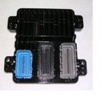
mefi5_LG.jpg
Chuck,
Can Hi and Can Lo come off ECM connector J3 the connector on the right in the photo. As Mark said they are a twisted pair from J3 to the service diagnostic connector.
Good Luck,Lou
 
Lou, Thank you so much for the picture. I must admit I don't think I have seen anything like this on the engine. I am so far over my head with trying to understand how all this works. I would really like to learn about this stuff, and will eventually use a mechanic for the installation. I just want to learn if what I want to do is possible (before I buy the PV 101 and harness) and how it all comes together.. Thank you, Chuck
 
icon1.png
Crusader Engine Data on to Garmin 4000 and 5000 series Chartplotters


Well here it is my friends ...

After lots of enquiries and research, finally we created a harness for the Crusader 8.1 engine data to show up on the Garmin 4000 and 5000 series Chartplotters.

1. The mate to the Crusader 20 pin CANBUS is a Deustch HDP-26-18-20SN on the engine side distributed by Ladd Inc. in the U.S. - approx. cost US$25.

2. The Garmin fitting is a NMEA 2000 Field Compatible Connector, part number from Garmin is 010-1104-00 for male (or 010-11095-00 for female), approx. cost of US$33.

3. On the Crusader side, data is already in NMEA 2000 format:

Pin 16 is for high data
Pin 17 is for low data
Pin 13 is for ground
(according to M. Schneider @ Crusader )

4. On the Garmin side, wiring assignment for the fitting is:

Terminal #3 is black and is for ground
Terminal #4 is white and is for high data
Terminal #5 is blue and is for low data
(according to Garmin Support)

5. Any decent marine grade 3 strand wire for data, estimated length of approx. 15 feet ( depending on application and run to helm)

6. No power run in the harness, only ground and data. Engine ECM has own power, as does Garmin separately.

Thats it ... Plug and Play. Engine data on the Garmin Dashboard screen. Fuel Flow, temps, pressure, voltage, engine hours ... etc. etc. etc.

Best to all

Allen​
 
Allen: Great information, my only problem is that I have Volvo Penta 8.1gxi engines. I was on this web site trying to learn something about the PV101 as there is very little available for VP. My suggestion is that you repost this information under your own heading. My chart plotter is raymarine E80,again no help for me. This is too good of info to be lost on my post. I wish I could get the same info that would match up with my VP engines!! Regards Chuck
 
my rig up might be very similar to your Volvo gas set up and your raymarine might have the engine data screen available essentially replacing the Murhphy, I was going to buy the murphy when I discovered that the garmin had the ability to display the same data. then when i learned the engine was putting out the 20data, I put the whole thing together and was told I was the first have the engine talk to a garmin, although crusader had a cable premade that would talk to raymarine. My point is that if your engine has the data already available in those pins and your raymarine has an engine data display page, you might be very similar in set up to what i was able to accomplish by simply connecting the two with the right fittings or pin connections . I spent most of my time talking to each company directly and some posts here and other locations helped but often the posts were not always correct. good luck my project was fun when it worked at the end and i enjoyed the challenge, The crusader gas engine was 8.1 and the data was in both j1939 qnd nmea 2000 formats . There is a maretron data gateway that converts those two sentence structures to talk to each other but in the end i did not need it . you are close and you might not need the murphy at all, allen
 
Allen: Thank you for the response. This project has been a challenge, and I was about to give up until I read your post. I had a mechanic read the gals/hr, with a Rinda diagnostic lap top. Which makes me feel the data is there. He connected to a connector (ford plug no. F5AB-14A666-A) on the engine with eight pins. I had murphy rep tell me I should not connect to the connector but wire directly. Unfortunately, I have looked but not sure I ever found out where to wire directly. The diagnostic plug has two wires twisted together, and I thought I might splice into them but just not sure.

I was told by VP rep that I have j1939 engines, but when I look at the engine info plate it says that it uses j1171 parts. I don't know the difference, so I am not really sure I have j1939.

My raymarine E80 has plug for nmea 0183 which I believe can be converted to nema 2000. It does have a screen to display mpg. Not sure how it would work for gph. Raymarine offers no help.

I would be happy if I could just connect to a PV 101, I just can't learn how to do it. I have talked with three VP dealer/mechanics, and I am afraid they know nothing about what I am trying to do. My boat is a 2007 Regal 4080 with twin 8.1gxi-G engines. I would appreciate any thoughts you might have. Regards Chuck
 
ok chuck I have done some research for you and your E80 raymarine has engine data paramenters on its screen already. It is also able to read NMEA 2000 sentence formats. So you are half way there just the way I was with my garmin. good so far. Now you need to know if your volvo is putting out engine data from its ECM in the NMEA 2000 format from those pins, You are most likely looking for 3 pins for high data low data and a ground on some multi pin quick connector near your harness area. If your Volvo ECM is outputting engine data in NMEA 2000 format your challeng is the same as mine and all you need to do is make up one cable with ends that match each device respectively. I was able to use a magnifier glass to get the name and serial number off of my CAN Bus 20 pin and order a mate from the states from a company called Ladd who distributed the electrcial connectors, Then I purchasded the chartplotter side from Garmin, In your case you need a raymarine fitting for their sea talk 2 or Nmea 2000 recepticle on the E80 and whatever you can find to match the engine end. In theory these can be crimped on or sliced but in my case I wanted to find the exact proper connectors to ensure water and moisture protection. You are very close to being able to succeed the way I did . Find out what format the volvo is putting out the engine paramaters in .... forget Nmea 0183 that is not what engines put out.... its either the 2000 or the J1939 and sometimes both of these are at the same time. then you do not need the murphy at all if you can confirm all this. you are not far from a soluction that willl work ... allenb

Now if your engine is outputting all the engine data in the old auto format called J1939 you can purchase a Maretron gateway device that will translate the old format to the new for about 300 dollars. I did not need that becuase the garmin and the engine spoke the same NMEa 2000 sentences.
 
chuck

this may be what you need if the engine and the raymarine are not both sending and recieving NMea 2000 sentence data

Maretron J2K100 - NMEA 2000® / J1939 Bridge (Engine/Transmission/Genset Gateway)

Maretron's J2K100 attaches directly into J1939 networks of compatible engines, transmissions, and gensets and converts the J1939 engine data to the NMEA 2000® marine digital interface. Critical engine, transmission, and genset data is then distributed throughout the vessel over a single cable where it can be monitored by any NMEA 2000® compatible display. All the information you need is available anywhere and everywhere you need it. compatibale with Volvo, catepillar and others, check our web site

allenb
 
I have a 740s connected to twin Crusaders via Crusader supplied synch cable between the engines and mnea2k network. Guages, tach, and fuel flow work, but I do get lots of alarms like Sub or Secondary Throttle, Warning Level 1, Warning Level 2, Maintenance Needed, Power Reduction, Engine Shutting Down, and Neutral Start. The engines are 2007 and seem to run fine so I wasn't expecting to see many alarms come out sontinuously. But you should be able to do this without a j1039 briidge if you're engines are outputting nmea2k messages.

What is the website you're saying to check?
 
Well Gentlemen I think with your direction I think I am on my way to get the pv 101 installed. Mackomark, your suggestion to test with key on fixed my problem. I was able to get like 2.5v and 3.0 volts from the twisted cable (not shielded) found on three diagnostic plugs. I am getting a generic cable and PV101 from company and will cut the wires from one of the plugs. Thought about using the J2k100, but Raymarine made me fill uncomfortable with this approach. Thanks to all for your time and advise. Regards Chuck
 
Has anyone had any experience trying to hook up a Murphy PV101 to a Ford Lehman 2715-E engine to read oil temp and oil pressure? Murphy says their MeCan product will translate an analog signal into a digital J1939 readable signal. They suggest using their EG series sensors.
 
Back
Top