Logo

V Drive Engine Alignment Tips

jon_allen

Regular Contributor
Hi Guys,
I'm working on a V drive boat (non Crusader). It's a big Block Chevy, and I need some advice on aligning the V drive flange to the propshaft coupler flange. There are two mounts on the engine and two on the V drive. There is a fair amount of movement in the propshaft: left to right and up and down. The engine mounts are decent and the cutlass bearing is tight. I would like some basic advice on how to perform an alignment on this setup. I suppose it is not much different in practice than a straight inboard but the access is really tight. I would like to get it right on the first try. Any advice would be greatly appreciated.

Thanks,
Jon Allen
 
Mine are Crusader 350s and the V-drives are 4500s but I would assume that alignment is pretty near the same for any V-drive to prop shaft.

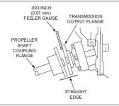
It is important that final alignment be done with the boat in the water.vdrive2.jpg

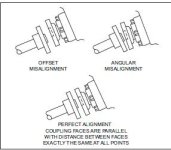
I have attached a couple of diagrams that show how to do it and a few mistakes that can be made.
vdrive.jpgProper alignment

From experience I can tell you that alignment is very important. Poor alignment will result in wear and tear on parts very quickly as well as, in some cases, unwanted noise !!!:D

In the case of my V-drives..the V-drive is firmly mounted but can move vertically and horizontally on the mounting struts until it is locked down and it is a combination of ensuring the shaft from the engine to the V-drive is within limits and from there it is just a matter of tinkering to get the prop shaft lined up.

To get the complete set up I would assume that the two aft mounts on the engine are also adjustable as well and once you have the shaft from the engine lined up very well with the top gear of the V-drive then the prop should not be a big issue..

Normally there is more tolerance allowed from the engine shaft to the top of the V-drive than from the bottom of the V-drive to the prop.

Good luck
 
I'm assuming by the number of mounts you mentioned that this is not a separate Walter drive but one attached to the engine. Yes they are a pain to get at. It's the same proceedure for alignment except that you want the tollerance to be as tight as possible. If you catch yourself saying "I think that should be OK", then keep going and get it better. You do not want to get down there and take it all apart again after a sea trial. I would say have fun but I know that's not going to happen so Good Luck, and I hope the first time's a charm and you don't have to redo!
 
Thanks Willow and Wood,
It is a direct mount unit. My main concern is the noticeable amount or sag at the propshaft while disconnected from the V drive. I need to center this before adjustment. Any ideas? There is quite a bit of play, left to right and up and down between the propshaft and tube. I've read about centering it on a ( feel basis and then supporting it). I cant (feel .003) so how can I expect good results by feeling the center of the propshaft?

Thanks
Jon Allen
 
Well I know there is sag when I disconnect my prop shaft from the Vdrive, about 1.5 inches. There will be some play up/down/left/right prior to hook-up cause the prop shaft exits through the hull and the exit point does have some play.

The important thing is to get the shaft and the Vdrive to meet "flushly" (is there such a word?).

It sounds like you should be looking for equal amounts of play in all directions prior to coupling the prop to the drive and not have any undue strain in any one direction.

As I said earlier, I only know about the Crusader and the 4500 Vdrive but I would think 'prop shaft to drive' would have pretty much the same methodology when connecting the two.
 
My main concern is the noticeable amount or sag at the propshaft while disconnected from the V drive. I need to center this before adjustment. Any ideas? There is quite a bit of play, left to right and up and down between the propshaft and tube. I've read about centering it on a ( feel basis and then supporting it). I cant (feel .003) so how can I expect good results by feeling the center of the propshaft?

Thanks
Jon Allen

As you note, the above diagrams attack the issue of shaft alignment with the transmission flange. That is 1/2 of the problem. It generally does a good job at vibration, if you have a propshaft that is not bent, and a flange set that is true. BEFORE the flanges are aligned however, the shaft needs to enter the strut(s) parallel to their bore. As you note, there is quite a bit of slop and it is not clear where in two-dimensional space to put the propshaft coupler, even before the engine is installed, much less lined up. If you do a great job at flange alignment and a poor job of strut alignment, the cutlass bearing will wear badly, and you might even get some metal to metal contact either there or in the shaft log. You may find that the shaft is hard to turn manually. So, what I am suggesting is to worry with strut alignment first, and its not particularly easy. You need to find that position of the propshaft that centers in the strut (with a new cutlass preferably). THEN, it needs to be checked that the shaft is reasonably centered in the shaft log. If that step is impossible, then the strut(s) needs to be moved, rebedded, reshimed, replaced, or "unbent". You can see that this is non-trivial, especially with multi-strut installations, with weak FRP hulls that need to be in the water for this step, or with unstable wood hulls that change dimensionally with water content. I would work with a diver that can monitor the shaft exit from the strut with an inside assistant that can try some positions of the flange end to optimize the shaft angle. Note that there is a pretty considerable propshaft bend from support at only the far strut. So, it will need to be raised up from that rested position, but shouldn't need much lateral adjustment from its sag position. You may also get some good feel from manual rotation of the propshaft, once a vertical and horizontal position of the flange is selected. This is in an effort to see how much cutlass drag is present. In the end, you want the lowest drag propshaft position.
In the air, at a factory or yard, during the strut install, the use of a laser is beneficial for lineup; the laser won't sag like end supported metal.
 
They way Dave has set up the plan for you is SO perfect....I can only attest to this fact, upon purchase our alignment was so poor that the shaft log had been abraided so badly we were EASILY in danger of sinking the boat from the hole worn into the side. Had the stuffing box let loose that would have been the last link in the major leak chain. " non - trivial " is a nice way to put it.
 
Jon, I use different sizes of wooden dowels or drill bits to hold the shaft in proper alignment to the strut as it goes through the tube at the bottom of the hull. It doesn't have to be perfectly centered in the tube but close. In the real world, I usually end up using a few different sizes of drill bits or dowels to hold the tube to strut alignment. This gives you almost no play at the log end and enables you to see if the log nut is riding the shaft. Do an initial alignment, then splash the boat, let sit for a day, and do the final alignment. Works for me.
 
Hi Gang,

Many thanks for your help. Woodie, are you placing dowels around the shaft in the tube so the shaft is perfectly centered in the tube? If so that sounds like an awesome technique. I don't know if I can use it because the exposed shaft between the dripless stuffing box and the coupler is very short and I probably won't be able to pull the dripless stuffing box forward enough to access the tube. I could probably do it with the coupler removed and then reinstalled. But I will try to avoid going that far. One other question I have, is there a preferred order for engine adjustment such as which do you adjust first ? vert. or horizontal?

Thanks,
Jon Allen
 
Jon:

The dowels work great when the hull has been hauled (from the outside, or the inside with the hose off).

I'm in the process of making a 'shaft holder' for this job. Haven't built it yet but here's the initial concept. a 1" piece of angle aluminum sits like an inverted V. On the pointy end, a v-groove is cut to hold the shaft. Either end is held by a small plywwod block. The small block is attached to a larger plywood 'leg'. Each leg sits vertically, along the stringer, and is 'c-clamped' to it.

The trick to making it work is to get the shaft centered in the log as DD and the others have noted. I'll use the coupler on the gear and just note the Up/DOWN & L/R deflections and center the shaft accordingly. Once the shaft is centered, moving the engine/gear to align it only required manual labor.

Anyhow, food for thought.
 
Hi Guys,

The dowels worked great for centering the shaft in the tube. I do have a question however. Is there any reason not to adjust the left to right offset position of the motor with the slotted engine mount bases or is it best to adjust via the four trunnions on the mount brackets? I think that the trunnions maybe frozen in their brackets.


Many thanks,
Jon Allen
 
depends upon which mounts you have. The 'standard' crusader mounts only allow L-R adjustments via the trunnions. sometimes, a bottle jack strategically located, can removed enough load that they will move easily.

If the mounts have slots, don't see why you can't use them. Just make sure to keep enough of the mount on the stringer. You also want to "center" most adjustments if you are going to relocate the engine. don't be surprised if things aren't 'perfect'; I've seen a few that were pretty good, most aren't.
 
i've used a come along and a bottle jack and a two by four to either push or pull the engine left or right.now i have been fighting shaft alignment also and have been getting vibration and slight rubbing, and my mechanic told me that the shaft flange can be easily bent if you need to remove it with a hammer to knock it off of the shaft and recommends to just replace it to assure it sits on the shaft properly. anybody ever heard of that before? it makes sense.
 
Hi Gang.

On this particular set up there are trunnions coming out of each of the rear mounting brackets which bolt to the V drive. There are bolts which pass through the V drive mounting brackets just beneath the trunnions. I have noticed that there is'nt a slit in the rear brackets like the front mounting brackets. With the bolts loosened I can't get any movement at the rear trunnions. What am I missing? It seems that there is no left to right adjustment at the V drive end. If this is the case then what do these bolts beneath the trunnions do?

Thanks,
Jon Allen
 
Hi Jonny,

The trunnions were frozen so I never got them to move. If I could do it over, I would support the engine, take off the mounts an free up the trunnions.

Good Luck,
Jon Allen
 
That's what I had to do when I re-aligned mine.

Aligning a coupling on a Vee drive has got to be THE number crap job in all marine repair!

Jeff
 
Back
Top