Logo

'75 OMC Stringer 225 hp Lift trouble

snocat_trf

New member
I have been fighting this outdrive for a year!!!! ARRRGGGHHH!!!

I am at my wits end with this thing, I can operate the switch to lift the motor and all i get is about a 1/2" of lift out of the lower unit, if I put slight tension on the lower unit and have someone operate the dash switch it goes up just fine. It also goes down easliy.

The only thing I can think of is that there might be too much clearance in the gimbal pivots to allow for the lower unit to pivor properly.

It seems like there is some bind in the clutch pack so i was wondering if I should find a second clutch pack as a donor to try turning down the diameters to fit in a set of needle bearings for it to rotate on.

Things I have checked and replaced:

  • rebuilt clutch pack multiple times. tried 30 wt oil and greasing as well as regrooving clutch plates and wearing in to steel plates
  • replaced lift motor, (I have 3 of them)
  • replaced solenoids as well as cleaning contacts.
  • replaced "ball" fuse and upgraded to a 50A plug in style
  • direct grounded lift motor to battery
  • direct wired solenoids to battery
  • removed gimbal caps and regreased and replaced cautiously to avoid any bind
  • removed clutch pack to manually to ensure lower unit pivots with no bind
  • replaced battery as well as wiring in two batteries in parallel to ensure enough amperage to operate motor
  • segment gear and drive gear
  • machined out a bronze bushing for clutch pack shaft to tighten up clearances to prevent bind.
  • greased everything in the lift mechanism to make sure there is slip on all surfaces
  • motor goes forward and reverse fine while not under a load.
I would appreciate anyone that has any tips for this and can help me out before I find a gallon of gas and a match!

Snocat_trf
 
If you look at a break down on Shop.Evinrude.com and go into the S.D. section and look at your tilt clutch assembly and find the worm gear where it first goes into the hsg you will see a little washer part # 309272. If it's it's not there it can cause the LU to bind when going up. I've had this happen to me before. This washer is infront of the worm gear.
 
from the looks of it, the worm gear shaft has two roll pins and one of them rides on the bronze bushing and one of them drives the worm gear... am i missing something?
 
Yes, both roll pins hold the worm gear to the shaft. Roll pins don't ride good against anything. They only hold things in place. Check the parts break down real close again. Also, if you had the t/t mtr off there is another nylon bushing that goes on the shaft before you put the hammer blow coupling on, part # 909513. Again, CHECK THE PARTS BREAK DOWN .
 
Last edited:
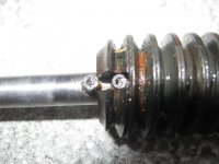
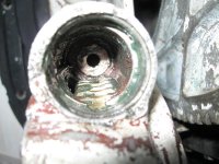
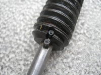
Here are a couple pics of the shaft worm gear and the way they assemble.

I always wondered if the part was made correctly as the front roll pin had been riding on the bushing inside the housing.

Does anyone else have a pic of how these parts should look when assembled?


3-24-2010 002.jpg3-24-2010 004.jpg3-24-2010 001.jpg
 
Something is definitely wrong here. The roll pin is not supposed to rub on the nylon washer that goes between the worm gear and the bushing in the housing. It looks like something was machined wrong here. Either the shaft or the worm gear it self. I wish I could be of more help but it's been 20 yrs or so since I worked on one of these and I haven't got any SD manuals or service bulletins anymore. But there is a little bell going off in my head about a service bulletin I've seen one time about the roll pin holes being miss drilled in the shaft. If you could find some old Stringer service bulletins some place you might come up with something.
 
Last edited:
well I could either make a new shaft, remove one of the roll pins or cut the slot deeper in the worm gear,(I am a toolmaker and have a mill and lathe at home as well)

I was hoping someone else could chime in on this one......I need HELP!

I need to get this working
 
I know a SD Guru up North who I called today but he was out. Suppose to be back tomorrow so if if find out anything I'll let you know. I too thought somebody else would chime in on here.
 
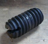
Here is a pic of one on Ebay with the slot cut farther back I just might set mine up and cut the slot deeper so the second roll pin clears

worm gear.jpg
 
Last edited:
I just looked at both picts that you posted. Looks like the orginal was mis-machined. You want to make the roll pins disappear so they won't rub on anything. I'll let you know when I hear from my Guru up North.
 
I set mine up last night and machined it back to clear the roll pins, It was through hardened, good thing for Carbide endmills.....I dont have the correct plastic bushings but I will machine out those tonight and try to assemble before dark to see if this cures the problem.

Thanks for the help....
 
Don't forget the little nylon washer pt # 309972 that goes in FRONT of the worm gear. Let me know what happens.
 
You probably already know what I'm going to tell you but if the tilt mtr is not off of it's mounting area now it will have to come off. When you get the shaft with the worm gear on it all assembled and when you put the hammer blow coupling on there is a little nylon washer on each end of it. Make sure they are there. My Guru said this would also bind it up. He couldn't remember any service bulletins about mis-drilled shafts but said he would look. Those little nylon bushings are pt # 310612.
 
I dont have those bushings on hand but I do have some teflon, delrin, and nylon rod on hand, I might turn them out of delrin, do you have any idea with the thickness of those is? If I remember, they are quite thin anyway prob around .030" or less.
 
My "guess" would be for the one washer that goes on the shaft and faces the worm gear would be about .035". The ones on each side of coupler are a little thicker but not by much. By the way, what did the end cap look like where the roll pin was sticking out ?
 
Last edited:
not sure what you are asking in reference to the end cap but here are some pics of the parts I have

repair kit.jpgend cap.jpg
pencil.png
 
I was talking about the originial end cap that came off the unit. If I keep conversing with you my memory is getting more jogged. That bracket you showed in the pict was made for when the snap ring area broke out in the housing that holds the end cap in. The bracket now holds the end cap in after you install the bracket by drilling some holes in the housing and bolting it to it.
 
Last edited:
Yes, my end cap needed to be replaced by this repair kit as One time I was out fishing and my shaft, worm gear, snap ring,and end cap ended up in the bottom of the missouri river, so when I went and ordered new parts, this is what I ended up with from the dealer.
 
So my goofey question still is what does the end cap look like inside when you had it all together and wouldn't go up with out an assist. I'm talking about the area where the roll pin was sticking out and not into the worm gear. ?
 
if you look at the middle picture in my post #4 of this thread of the housing, you can see the bronze bushing that the roll pin was rubbing on.
 
Like I said it's been 20 yrs. I now see where the roll pin was rubbing against bushing # 308634. By cutting the worm gear gruve and installing a new bushing in the hsg along with the little nylon washer you may have cured your probs.
 
I put in the plastic washer in front of the worm gear, i was all set to get in and pull the motor and put them in front of and behind the hammer blow coupling when a big rainstorm blew in. I should have this thing in the garage so i can work on it and not get wet.

I might try pulling the motor tonight.
 
this is just not working out for me, I replaced all the plastic washers and made sure the motor is not binding by measuring all the projections on my motor with the original Prestolite one just to rule that out.

If you just put slight pressure on the motor it will lift but it will still not lift on its own.
 
you want to try drilling a hole thru the plates and installing a bolt and nut to freeze the plates?

Cause thats what is slipping.
 
Chief, I've never heard of that being done but if it works like they say " You learn something new every day". Good idea tho'.
 
You got to look at the clutch pack as sorta a motorcycle clutch, believe me i have seen plenty.

Did you try tightening the clutch pack mine is newer then yours, 86'. Also if you over tighten the cover of the clutch pack you can bind the shaft also. I use 2 gaskets under the cover, remember the gaskets don;t seal the cover the o-ring does.

I Hope you don't mind me jumping in here cause i ain't the garu from the north you mentioned.

However i have been following this thread and so far you have been right in what you are doing.

You don't need a thick nut and bolt, 1/4 inch maybe a little bigger.

Heres what i would do if it were my boat, i would remove the clutch pack, and see if you can tighten up the pack, maybe yes maybe no, cause it might be the one that has to be pressed on, i used a vice with a sorta jig set up.

If you can't get it tighter or you never fully took it apart and cleaned each disk then you might want to try the bolt trick it works.

But be aware i am not recommending this, and the deisgn is such of the pack that if you strike a object the pack is supposed to give and allow the drive to move up thusly not causing injury to the drive. Thats the theory anyway, and design.

So hypothetically if a person were to freeze the pack with a bolt the drive can't move if it were to strike a object.

Good luck !
 
Back
Top