Logo

engine will not shut off with key

mmarks00

Member
hey guys i have a aq125b engine in my 81 bayliner mutiny, when i turn the key off the engine will not shut down.i have to remove the purple wire from the + side of the coil and then it will shut down.i checked the ignition when i turn the key to the on postion i get power to the coil and then when i turn the key off there is no power to the coil.only when the boat is running the power to the coil stay hot with the key turned off.what do you think:confused:
 
Off the back of the alt there is a small wire with a small black gizzmo on it. This wire tells the alt to charge and is one way, to the alt. The black gizzmo keeps the power from back feeding the Ign system. It's bad and is allowing power to feed the ign. You need to replace this wire with the diode inside the black gizzmo.
Not very techy but it gets the point across.
 
Yep, Volvo calls this a resistor, but it is actually a diode... possibly has a resistor also. I have changed several of these for the very same reason.

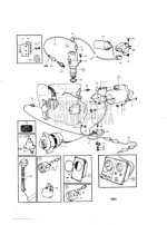
Here it is shown as SEQ # 43.
It's a pricy little bugger, so the diode fix may be a cheaper route to go.
Make up two of them, so you have a spare.

7062.jpg
 
7061.jpg

A resistor might do.
This is a plain US (Coats Guard??) issue.
The rest of the world had simply a charging light (resistor!!) in the instrument panel
 

Attachments

  • elsys120.jpg
    elsys120.jpg
    38.4 KB · Views: 606
The disadvantage of using a resistor is that it keeps on 'burning' when letting the current through, and sooner or later burn out like a light bulb!
One may use the 'original' one that comes with a price, or the simple diode solution to about 2$.
Never had any problems when changing to diodes.
As an extra tip, put it in a shrink tube to protect from moisture.
PS: Current should flow TO alternator and block from.
 
PS: Current should flow TO alternator and block from.

If you are not familiar with diodes, one end always is marked, usually with a band...sometimes with an arrow.

If its banded, that end is the end that the current (conventional) will flow out of. The banded end, per above, should "face" the alternator.

If an arrow, is should "point" to the alternator.

The diode should be rated at least 100Volts. There is almost no price differential between a 50V and a 100V diode.

The biggest challenge in making one of these yourself is getting reliable connections. The best way would be to solder it, however, if you are not experienced in soldering electronic components, don't try. Next best would be a crimp connector, preferably one with heat shrink insulators. (Available at most marine stores) Get one sized to the wire. You will find that you will probably have to double the wire on the diode leads back on itself for 1/4 inch in order and flatten the end with pliers in order to get a good crimp in the connector. Cover in sleeving, heat shrink if possible. If no heat shrink, fill the ends with a sealant.
 
Eduardo, if this were simply a resistor, and if it were to fail, why then do some of these engines continue to run when the ignition supply is cut?
A resistor allows for bi-directional DC current flow.

A failing diode is more likely to allow reverse flow of DC current that keeps the ignition engergized!
Yes/No?

A dioded replacement has done the trick for me several times.

I'm open to learning more on this!
 
All great ideas to cure the problem but when one considers it's almost 30 years old and cost $30.00, at $1.00 a year I'd put the same thing back on if it is available locally. If one wants to go to all the trouble of finding the diode, building the wire however one wants to build it, crimp or solder then try and seal it up good enough to be in a engine/bilge area, $30.00 is way cheaper in my mind.
 
Eduardo, if this were simply a resistor, and if it were to fail, why then do some of these engines continue to run when the ignition supply is cut?
A resistor allows for bi-directional DC current flow.

Ricardo, an engine would keep running if the resistor is shorted because of backfeeding the ignition coil from the alternator field coils. But if the resistor would become open when it fails, then there would be no problem in stopping the engine with the ignition key (however, the alternator probably had stopped charging in this event).


A failing diode is more likely to allow reverse flow of DC current that keeps the ignition engergized!
Yes/No?

Again, "yes" it if the diode becomes shorted when it fails, but "no" if it becomes open.


A dioded replacement has done the trick for me several times.

I'm open to learning more on this!

I do not object to diodes. I understand their merit and know they work better than resistors, since they act like an electronic switch. My whole point is that the original rubbery black gizmo from VP is a resistor, not a diode.
 
Eduardo, if this were simply a resistor, and if it were to fail, why then do some of these engines continue to run when the ignition supply is cut?
A resistor allows for bi-directional DC current flow.

A failing diode is more likely to allow reverse flow of DC current that keeps the ignition engergized!
Yes/No?

A dioded replacement has done the trick for me several times.

I'm open to learning more on this!

Diodes are normally nominated in Voltage. In short the Voltage it is capable of blocking. On the other hand all diodes has a certain leakage, normally in %. If you choose a diode with too high voltage, the leakage might be too high, and engine keeps running.
A diode normally fails in the way that it shorts, current goes both ways.
On the other hand if a lower voltage diode shorts, the amps going to the engine might not be enough to operate the coil, it will work almost as a resistor.

The 'European' system uses a 3W bulb as resistor, if remembering right. That gives about 0,3 Amps, enough to get the alternator started, but not to feed the coil. When that burns off, alternator will not start when engine is started, but engine will stop normally by the key. Engine will consume from batteries and stop when voltage gets too low.
The original US resistor is designed to short out when it fails. Alternator will start charging, but engine will not stop or drain the batteries.

I have seen all kinds of solutions to 'fix' this problem.
Light bulbs in engine room, manual switch on instrument panel, you name it.
 
bought the diode and installed it to the alternator and boat now starts and turns off every time.took the boat out for a test run and no troubles thanks guys.
 
Hello all. I had this same problem with my 97' Wellcraft with a 5.7L Volvo. I searched the web long and hard, and it was this forum that led me to the answer. Thank you guys. What I found was the was no diode off the back of the alternator. I found a gray wire coming off the coil that a soft rubber sleve about 2" from the coil. Inside that sleeve was were the diode was. I simply bought an .80 cent 3amp blocking diode from Radio Shack and pigtailed onto the endo of the existing diode wire and hooked it to the coil the same way the original was. Now the boat shuts off everytime. Thanks!
 
Had same problem with engine not shutting off with key with my 1997 Wellcraft with Volvo Penta 5.7. Tried the Volvo resistor part, did not fix the problem. Removed alternator and had it tested - tested good, and this was baffling. Adding a diode to the excitation terminal (ECS) of the alternator did not enable engine to shut down. Got low in the engine compartment and found that the positive battery connection to the starter had shorted to the positive connection to the solenoid, essentially by-passing the ignition switch. I re-oriented the wiring so it could not short and shrink-wrapped the damage to the wiring. Just wanted to add this information to help someone else, as I found this thread very useful in trouble-shooting my own problem. This short occurred after 17 years of age on the boat, and with the original factory wiring. The problem was also intermittent, so it was hard to figure out. The engine might shut down by key 1 in every 5 times with the ignition switch.
 
Back
Top