Logo

chrysler 360 ignition nightmare

egg harbor 1977

New member
Help needed here. I have a 77 Egg Harbor with chrysler 360s. Port motor runs perfect. Starboard motor burns out ignition coils and hunts at 2500 rpms. I have replaced the Coil, ECU,Ballast resistor, Cap. Rotor and Ignition switch. It reads 13 to 14.5 volts contiouous at idle thus screwing up the whole system. It does run only when holding the ignition to start position and stalls out when I put ignition in run position. This is killing my season any help would be appreciated. Kevin
 
Okay. Here's the deal: When you hold the key on like that, you're sending 12 volts directly to the coil from a terminal on the solenoid. Let off the key and the usual ballast resistor circuit takes over, delivering about 7 to 9 volts. If this (RUN) circuit is not working due to a bad resistor or bad wiring connection, then the motor starves for enough volts to make proper ignition.

Want a guaranteed fix? Here's what you have to do:

1. Buy a 45,000 volt coil designed to run on 12 volts from Jegs or Summit Racing (on-line)

2. Buy a ballast resistor part # ICR11 from NAPA

3. Find where the 12 volts comes in to your existing ballast resistor and wire the new one in its place. Be sure to leave the wire from the solenoid terminal to the coil (see above) in place--it might be necessary for starting (with some ignition circuits). And use the screwed on connection that come with the resistor--no more spade connectors!

4. Install the high performance coil and go boating!

This fix that was developed by my buddy John S. and it made new boat out of his!

Jeff

PS: One more thing to check: At the back of the motor is a connector that joins the boat's wring harness to the motor's. Make sure the contacts are clean and lubricated with electrolytic grease.
 
Last edited:
I have been looking and reading posts for a couple of days now and there is some great information, but I still looking for a wiring diagram. I bought the manual from this site, but it only shows wiring for points, I have elec control unit with the ing pickup.
I have a M360 (RH) that someone repower a 1974 23' Chris Craft Lancer I just bought. The engine was still set up for a double station and who ever installed it scabbed the engine harness together with the boat harness, using wire nuts even a couple of clips. :(
I plan to change it over to Fastjeff's method, Buy a 45,000 volt, full 12 volt hot rod coil from Jegs or Summit Racing (on line). Then go to NAPA and buy a part # ICR11 ballast resistor. Wire it in line (using bolted terminals. not spades that can fall off) and your motor will run great. Don't leave out the resistor or the coil.
I sort of understand the resistor and what it does, but I'm not sure of how it is wired, I looks like there a two (2) wires from the riststor to the ing switch. Is this correct? Were can I find a wiring diagram for my motor with elec dist?
 
The stock ignition system on those motors was a bit confusing to be sure. To simplify things:

1. You want to see 12 volts at the ballast resistor in RUN and,

2. You also want to see 12 volts at the resistor when you hit the starter.

Ignore the other wires on the resistor--they go nowhere in most cases.

Jeff

PS: Attached is a wiring diagram for Chryslers.
 

Attachments

  • WiringChrysler[1].pdf
    147 KB · Views: 1,334
Last edited:
Okay, I'm getting closer. I have the wiring figured out and it's trying to fire with the old resisitor and coil. I still need to set the timing, but first, I need to set the gap between the Reluctor and the Pickup. What should it be set to?
I have ordered the flame thrower and the napa resisitor.

Thanks a bunch
 
I have installed the new napa resistor and the flame thrower. What do I do with the green and blue wires coming from the elec control unit? I hooked them back to the new resister, with eye and screws along with the other leads. Is that correct? They that curent should still a resistince, right?
 
Jeff, just curious... Chrysler was first on board with VR ignition... perhaps they developed it... I don't know. But I believe they were first on board.
The Mallory YLM series to this day uses VR ..... and it has been a tried and proven system.

However, for this 1977 boat, the OP is saying, and I quote here: "I have replaced the Coil, ECU, Ballast resistor",
What would he be calling an "ECU" in a VR system, unless this is not VR?
Is he refering to the VR sesnor or pick up unit?

Just curious.

.
 
The wires on that ballast resistor is confusing all right. Take a meter and find the 12 volts input to it, then cut that wire and splice it to your new resistor. Also, there is still a 12 volt wire going directly to the coil from the starter solenoid. Don't forget to include that one or it won't have any spark while cranking.

Not concerned on the VR vs (I forget). The setup you soon will have works super!

Jeff
 
HOLD IT! I was wrong (again). One of the wires coming it to the ballast resistor is used to power the ECU (black box). Here's a crude sketch of what the stock system looks like:

IGNITION WIRING--smaller.JPG

Jeff
 
Jeff, I have two small threaded studs on my starter solenoid and I see there is only one on your drawing. I hope I'm not to much of a pain, and if I would have marked the wire better when I took everything apart, I be a less pain. :) :)
 
Sorry. Left that other stud off the drawing (since it's for the starting circuit). The stud that goes to the coil is the "I" stud.

Jeff
 
Another question.
When I pulled my distributor out orginally, the tab with the 90 deg. upperward bend, which locates the cap, was at the back of the motor, which puts the pickup to the rear also. According to all the drawing and diagrams the rotor points forward when #1 cylinder is TDC. Is this correct.
The cylinders are firing, but not in the right order, and I can not see what I'm doing wrong.
Glenn, technically, it makes no difference in how the distributor is indexed with the cam gear, nor where the distributor housing is indexed, as long as we begin our spark plug wire indexing correctly for the firing order.
However....., most/many of us will do as you suggest, and index the distributor housing to suit our needs, and also index the rotor to aim towards # 1 cylinder while @ TDC.... but since #1 TDC comes around twice (per 4 engine cycles), the TDC that you want must be during C/S (compression stroke) only.


Here is the Std LH Engine Rotation 360 firing order beginning from #1 cylinder.
If you'll notice, they do not have the distributor indexed as to aim the rotor towards # 1 cylinder.
You can simply re-arrange the indexing it you wanted to.

170934_360_firing_order_1.jpg

.
 
Last edited:
That diagram is the same one I have been using, but my motor turns CW (looking at the flywheel) which make mine a RH and the distributor turns CW also. So maybe my problem is I using the wrong diagram?
 
I waiting for my new pickup and reluctor before I try again. I have been going by the diagram under my plastic cover, which is also the same one Jeff posted on 5/11. What's up with those diagrams? Are they looking at the front of the motors for the rotation?
 
See posts #13 and # 19 again.

What's up with those diagrams? Are they looking at the front of the motors for the rotation?
Who knows what they are doing, but they should not be determining engine rotation while viewing the front!

Marine Industry Standards dictate that ALL engine rotation is determined as though viewing the "Flywheel End" of the engine.
Car/truck and most Port side engines are standard LH engines.
The exception to this may be the odd, wierd, unorthodox Chris Craft determination and engine mounting orientation.
Pay no attention to the CC information!


Image that Jeff posted for a standard LH Rotation engine:

attachment.php


Image that I posted for a standard LH Rotation engine:

170934_360_firing_order_1.jpg
 
I mentioned CC just in case you happened to read any CC information.

OK..... the image appears to be showing both the small block Chrysler and the big block Chrysler.
(this is a .pdf file, and I'm not sure how to copy and post it for us)

Cylinder #1 will always be at the front of an egine. Front meaning as if it were installed in a car/truck.
Even if the engine is fitted for a V drive, front of engine is front of engine, and all day long.

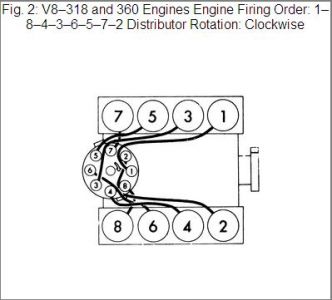
Note the cylinder numbering of the two images to the left......... #1 will be at the front.
The distributors on these two engines are at the rear of the engine... I.E., 318, 340, 360.

Note the cylinder numbering of the two images to the right....... #1 will be at the front.
The distributors on these two engines are at the front of the engine.

This is the difference between SB and BB Chrysler.
I believe that you will want to use the images to the left.

Here's another aspect of the REV and Std rotation engines:
I'm not aware of any distributor driven oil pump that is proprietary for a REV engine.
Therefor all oil pumps rotate conventionally.
This means that all distributors must also rotate conventionally, regardless of Engine Rotation.
Only the camshaft "drive" gear, and the distributor "driven" hypoid gear "cut" change for a REV rotation engine.
This keeps both oil pump and actual distributor rotation STD.

The spark plug wiring orientation, and the firing order, changes at the distributor cap for a REV engine.
The distributor won't know the difference!


And as if that wasn't enough..... there are several ways to drive a camshaft, and this depends on the vintage.
  • Chain and sprockets (which keeps cam and crank turning the same rotation... whether LH or RH)
  • Double gear (which reverses cam rotation (from that of crank rotation), back to normal in a REV engine)
  • Double gear (which reverses cam rotation for either LH or RH engine)
  • Four gear set-up (which keeps cam and crankshaft turning the same rotation... whether LH or RH)
Again, this depends on the vintage.
To my knowledge, not too many are using gears these days.
I could wrong on that!

I think that the key for you, may be in understanding the correct engine rotation determination procedure, and that the distributor will rotate Std no matter if LH or RH engine.

Again, always view this as though facing the flywheel end, and you'll have no problems.

.
 
Glenn, I just caught this.
............
This diagram is the one that has me backwards. My engine and dist. both turn CW.
Your ignition distributor will turn CW..... no arguement there!
Now, if your engine is indeed turning CW, when viewed from the flywheel end, then you indeed have a REV RH Rotation Engine.

However, if this is a Std LH rotation engine, it will be turning CCW when viewed from the Flywheel End (not CW).

When viewed from the flywheel end..... CCW = LH..... CW = RH.

Hope that helps, rather than further muddy the water.

.
 
Looking at my fly wheel the engine rotates CW and it has the extra housing under the disb to hold down the gear. I got the new pickup and reluctor installed today, set the firing order to 1-2-5-7-6-3-4-8 and she fired right up, and sounds good. I don't have water hooked up so I didn't run more than a minute. I do not know what year this motor is, tag reads; Model # M 360BWR15-015 and Serial # E-576326
When I get water and timing set, I post a video. Thanks
 
Back
Top