I'm in the last stretch of getting these engines together. I'm trying to figure out the wiring harness for the new ignition. The new engines have Mallory YLM624AV Breaker-less Distributors, Mallory Pro Master 9-29723 internally resisted coils and Edelbrock 1409 carbs with electric choke.
Questions:
1) Is the orange accessory wire ignition switched? I need an ignition switched 12 volt source for the electric choke.
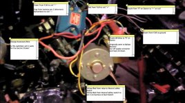
2) The gray electronic tachometer lead (Pin 2) is connected to the coil "-" terminal as stated in the service manual. The Mallory diagrams clearly call out connecting all wires originally connected to the coil "+" terminal but say nothing about the coil "-" terminal. I'm guessing this is the only place this could connect. Is that it is correct?
3) With the internally resisted coil, I now have the Yellow & Purple harness lead connected to the starter "R" terminal an the purple wire from the starter "R" terminal to the coil "+" terminal. The Yellow & Purple originally went to one side of the ballast resistor with the purple wire from the coil going to the other side of the resistor and the "R" terminal on the starter. I'm just closing/cutting off the unused pigtail.

Anyone familiar with this set up? I'm also curious about how the electronic tach works and what the yellow wire on the purple & yellow connector does. Is the yellow the exciter on the alternator?
Questions:
1) Is the orange accessory wire ignition switched? I need an ignition switched 12 volt source for the electric choke.
2) The gray electronic tachometer lead (Pin 2) is connected to the coil "-" terminal as stated in the service manual. The Mallory diagrams clearly call out connecting all wires originally connected to the coil "+" terminal but say nothing about the coil "-" terminal. I'm guessing this is the only place this could connect. Is that it is correct?
3) With the internally resisted coil, I now have the Yellow & Purple harness lead connected to the starter "R" terminal an the purple wire from the starter "R" terminal to the coil "+" terminal. The Yellow & Purple originally went to one side of the ballast resistor with the purple wire from the coil going to the other side of the resistor and the "R" terminal on the starter. I'm just closing/cutting off the unused pigtail.

Anyone familiar with this set up? I'm also curious about how the electronic tach works and what the yellow wire on the purple & yellow connector does. Is the yellow the exciter on the alternator?


