Logo

Crusader 350 Reverse rotation question

joeld98

Member
I've just about buttoned up my port engine an started scavenging parts off of the starboard engine when I noticed both distributors were the same model. I visually inspected the worm gears and confirmed one part number in the service manual.

I of course bought one 624 AV and one 624 BV with the reversed gears.

Am I correct that the Crusader Model 350 454 C.I.D circa 1997 used the same distributor with the same gear for LH and RH rotating engines? If so, does the worm gear pushing up on the distributor generate pressure against the hold down bracket?

I also have no idea what gearing the new long block reverse rotation has since I order them with the tin ware installed. I'm going to try the process of elimination, but was curious if anyone knew who used reverse rotating distributors?
 
I'm not aware of any Gen IV that spins the cam the opposite direction. A gear driven cam is used on "reverse" engines.
Therefore, you should not have to worry about "reverse" distributors.
 
I'd call whoever you bought the long block from and ask them who's cam they used. That will dictate which gear the distributor needs. 1997 vintage is the Gen V - Gen VI timeframe. All of that class that I've seen were ALL standard (LH) rotation.

One thing for sure, if you try to install a distributor with a "reverse pitched" gear, it won't fit.

On the "standard" distributor, the cam gear will apply and upward force to the distributor gear. There should be a thrust washer between the gear and the distributor housing. That upward force should be retained by the hold down bracket.
 
Please correct me if I'm wrong here..... but I recall that there are several methods used to rotate a camshaft for a reverse rotation engine:
  • Drive and Driven gears with twin idler gears (cam runs reverse...same as crank)
  • Drive and Driven gears only (cam remains stnd rotation)
  • Chain Drive (cam runs reverse also)
If the cam is kept in Stnd rotation, two YLM 624 AV's can be used.
If the cam is run same as crank, the YLM 624 BV is used on the Reverse rotation engine.

What remains the same, is that the oil pump in each engine will remain standard rotation, therefor both distributors will turn in the standard direction, regardless of camshaft rotation!
I believe that opposite cam drive rotation is pretty much "old school" by today's standards.

So in essence, the only difference between the BV and AV will be the distributor's "driven" gear. (both cam and distributor gear-cuts accommodate this camshaft rotation difference)

Up-lift should be the same on either, so you will have little concerns re; the hold down clamp.
You will note that either the BV or the AV use the thrust washer between the gear and housing.
If these gears were to place a "down-load" on the shaft.... an entirely different thrust affair within the distributor design would be necessary.

BTW, these are helical cut gears.

IMO, you made a great choice.... the YLM 624 is a Reluctor (VR) style triggering at it's best! These units rarely fail!

FYI and a suggestion: if you have not yet installed these engines, I'd strongly suggest that you mark off your Harmonic Balancers up to approximately 35 * BTDC!
The STBD engine will be marked CCW of TDC (opposite).
This will give you the markings necessary to time your engines for TAT.... (total advance timing) of which will give you more power potential.
If specs are followed, this will also reduce the likelyhood of Detonation caused by too much TA.

I would NOT suggest the use of the digitally advancing timing lights for this type of ignition system........ you'll want to see this in Real Degrees and in Real Time, IMO.
See your OEM specs for your TA and the rpm at which it is to be Full In! Note that BASE advance is rarely shown on an advance curve, and must be added.

Hope that you don't mind more info than asked for!

Have fun.... good luck!
 
Last edited:
Sorry, that was a typo. They are Gen IV Circa 1987.

Thanks for the detailed response Rick. I appreciate it. I'm actually trying to learn something as I plod along vs. just getting it back together. This information is very helpful.

I'll check, but I think I have the plain old no frills inductive timing light. When you say "Real Degrees and in Real Time" are you referring to looking at the engine vs. a LCD read out or something? I would not know how to use such a tool. I'm still coming to terms with not needing a dwell meter. :D

The second AV is en-route, should have the starboard engine together in short order.

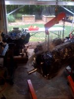
Here is the work in progress in my hoke-poke shop. The port engine is on blocks near the door, the stbd is on the lift getting ready to set on the stand. You can just make out the A frame I built to get the engines out of the boat. It's set up now for loading the trailer, I flip the I-beam so that the braces are on top to get full left to right movement in the cabin.
photo.jpg
 
....................
Thanks for the detailed response Rick. I appreciate it. I'm actually trying to learn something as I plod along vs. just getting it back together. This information is very helpful.

I'll check, but I think I have the plain old no frills inductive timing light.
When you say "Real Degrees and in Real Time" are you referring to looking at the engine vs. a LCD read out or something? I would not know how to use such a tool. I'm still coming to terms with not needing a dwell meter. :D
While I get some flack from the guys who love to use their Digitally Advancing timing lights, there is part of this that may not be understood.

The D/A timing lights are great...... and when used on a system that incorporates an ECM/ECU that receives engine data input from sensors and then controls spark advance "electronically", the control module can/may accommodate for any small errors.
These systems require a BASE advance only for initial ECU/ECM data.

With a mechanical advancing type ignition, there is little margin for error.
The advancing is done via a mechanical centrifugal system...... No control unit that senses "knock", engine temp, etc.
Once set up, this advance curve will be consistant and progressive per engine RPM!
Only wear and/or rust/corrosion is likely to change this!

When I suggest Real time/Real degrees, I'm referring to the ole strobe type light being used against a timing tab and real crankshaft degrees that have been marked off onto the Harmonic balancer.
When strobed, these give you real readings.... and do not rely on an electronic algorythm as per the D/A timing lights!
IMO, this equates to less chance of user error, less chance of equipment error and/or undetected equipment failure, etc.
It is not a risk that I am willing to take, sinse total advance in the correct range is so dam important for performance.
However, and IMOO, more importantly is the potential damage that TOO MUCH TA can cause an engine!

Most DA timing lights can be used in strobe mode only, I believe.
All you need is for the tab and balancer to offer you these markings.
It is extremely simple to do!

It's your call..... I'm simply suggesting what/how I would do this myself.

BTW, I learned much of this in the 60's from a man who was then, the oldest drag racer in America (72 years old at the time).... Mr. Vic McCrosky in Gresham, Oregon!
He was nice enough to allow me into his shop while he tinkered with his B gas dragster.
I think that he noticed my interest, since I had already become a SBC enthusiast by that time.
Vic just nudged me some by explaining Ignition, camshaft and crankshaft indexing....... piston combinations, cylinder head charcteristics, etc.
Of course there were no D/A type timing lights back then....... Strobe ONLY!
The hot ignition systems were Magnetos, fuel injection systems were not timed, No ECU's, and so on.
Quite different these days, but many basics are unchanged, and many of these principles can be used today! :)

Marine specs are certainly different, and I'd never advise anyone to rely on info from automotive "Gear Heads" and/or "Machinists" alone!
Not unless they have hands-on marine cruiser experience including owning their own cruiser type boat.
The basics as for Ignition timing, phasing/indexing components, etc, are very much the same in procedure only.
Specs will always be different!
Point being on that..... is to caution those of us taking advice from primarily automotive enthusiasts!


.
 
Last edited:
I am trying to follow this, having a similar issue. 26 @ 4000rpm is my spec, I have a standard mallory electronic ignition system, no computers. When timmed with a light @ 4000rpm, it equates to 3 degrees. If I time it to 8-10, the engine runs much better. What am I missing here?
 
You mean when you check the timing at full advance, it is 3 degrees?

BTDC or ATDC?

Maybe, if you describe the setup you are using to measure the timing, we'd all get a better sense of what's going on.
 
I am trying to follow this, having a similar issue. 26 @ 4000rpm is my spec, I have a standard mallory electronic ignition system, no computers. When timmed with a light @ 4000rpm, it equates to 3 degrees. If I time it to 8-10, the engine runs much better. What am I missing here?
Yeah, something is wrong with that reading. You may be using a digitally advancing timing light! Yes/No?
I know that there are those of you who love their Digitally Advancing timing lights. I don't want to offend anyone who prefers to use this type. Do so if you are confident in your skills and the accuracy of your digitally advancing light.

But with your (2wind) Mallory mechanical advancing system, I don't believe that it is necessary.

What I suggest (as in my previous post), is that we mark off the harmonic balancer up to about 35* clockwise of TDC for a LH rotation engine...... Counter-Clockwise for a RH rotation engine.
When strobed the marks with a Standard Type timing light, these degrees are contrasted against the ZERO notch in the timing tab (same as with the D/A timing light).
Our spark advance reading is as usual...... BTDC!

With the standard light, just plain physics allows us to read this in Real Time/Real Degrees! :)
At a given RPM the mechanical system will stop advancing. This is your "Full In" RPM and amount of degrees BTDC..... aka TA (total advance) or aka TAT (total advance timing).
This is the spec that is very important to squeeze the most out of our engine, yet fall into a safe range to avoid Detonation.


BTW 2wind, are you certain that your specs call for 26* Full In @ 4k rpm?
That 4k RPM seems high for full in..... and 26* seems low for 4k RPM for a 5.7L marine engine!
 
Last edited:
the model # is 50-473-07, I verified the spec. I used a standard light, ran it up to 4k. then checked where It was at at idle, hence 4 deg.
 
So it is 3 deg at 4000 rpm and 4 deg at idle?

If so, I'd pop the cap off and check the advance mechanism inside the distributor.
 
2wind, we're actually Hi-Jacking joeld98's thread here! :(
Why not start a new thread specific for your engines and particular ignition questions?

joeld98's ignition system is entirely different from yours as well.
Yours will be ECU/ECM controlled........ joeld98's are mechanical!
We can start fresh, and cover much of what you'd like to know! :)

Mean time, have your OEM specs ready... we can walk you through the basic procedure for setting/checking this critical part of your ignition system.

Let's further this in a new thread, please!
 
Last edited:
I agree that 26@ seems low, and 4k seems high. But the its propped per book at 4800 - 5200. the motor turn 300 horses supposidly. Is there a way to time this thing with out taking it to 4k?
 
4k rpm is above where we generally concern ourselves with Detonation. It is also above where we'd normally be operating our engines! At least for ME, it is!

I'm probably being very redundant here, so forgive me is so......, but Detonation is one of the more destructive forces against our expensive gasoline Marine Engines.
Proper fuel/air mixture, proper ignition timing, proper loading of the engine, etc., all play a very important role in effecient operation!
The RPM range where this Detonation potential is at it's greatest, is usually at the RPM at which we cruise at/near.
This is why (for me, anyway) a TA Full-In spec @ 4k rpm is somewhat meaningless. IMO, that is!
I'd rather concern myself with a TA Full-In spec @ approximately 3.2K RPM..... give or take an rpm or two!

If the advance takes TA further, then I have no issue. At 4k rpm (for example) we could probably throw 32*/34* at this, and have no issues!

Much of this also has to do with the piston selection that the engine builder used.
A full dished piston offers ZERO Quench Effect, whereas a Quench Effect cylinder configuration reduces detonation potential...... and we can generally throw more TA at these engines.

.
 
Back
Top