Logo

1981 280 tilt wiring question

mmarks00

Member
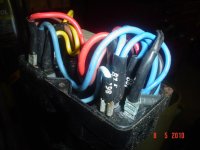
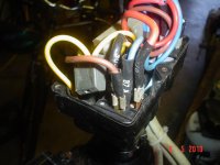
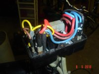
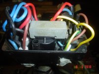
hety guys i have a 81 bayliner with the 280 out drive when i bought the boat someone has been doing work to the wiring on the tilt unit.looks like they may have wired the two relays wrong and melted a few wires.i removed the old relays and checked to see if the motor worked for the tilt.it will work when i test it directly to the battery it will go up and down.now for the big question i tried to rewire the relays using the book and the wires do not look the same.wondering if any one has a picture our a diagram of the tilt unit.thanks
 
Re: 280 tilt wiring question

i would like to say thank you very much.i am new to the boating world and this is my first fixer upper and this is the best place for help.everyone here has been real help full in me getting my boat running,just wanted to say thanks.
 
Re: 280 tilt wiring question

I should point out that the adjustment of the cutout switch i.e., "end position switch" is easy, but a bit fussy. It's not obvious, but the mounting for this switch also doubles as the adjustment. Make sure this switch works before powering up the unit for a test.
Wiring this switch incorrectly is a source of amusement. If you aren't familiar with the nomenclature... N.O. is the normally open contact, while N.C. is the normally closed, which means that there is continuity between the C and NC when the plunger on that switch is expended and continuity between C and NO when the plunger is depressed.
 
Last edited:
Re: 280 tilt wiring question

i would like to say thank you very much.i am new to the boating world and this is my first fixer upper and this is the best place for help.everyone here has been real help full in me getting my boat running,just wanted to say thanks.

You are welcome. I hope you get the boat up and running soon and start enjoying it. Fixer-uppers are only fun for a short time, and the fun usually ends when the bills keep piling-up and you see no progress....;):eek:
 
Last edited:
Re: 280 tilt wiring question

ok tried to wire up the tilt yesterday and everytime i hooked up the ground wire to the relay on#87a to #85 the fuse would blow on the power side.question i have the two wire motor.is the #87a on both relays always hot .when i put the test light on #87 and #87a on both relays there is power at all times. then i try to gound out 87a it blows the fuse .i am stumped
 
Re: 280 tilt wiring question

Use only the two wire motor schematic, or you will get easily confused.

The top micro switch gives continuity to the negative side of the motor circuit.
When the "vice rod UP travel" reaches it's limit, this circuit breaks...... the motor then stops..... and the Amber light at the helm goes out!
The relays, via the other side of the micro switch, take care of this continuity for the "vice rod DOWN travel".

It's a complicate little system...... but works well so long as the relays and the micro switch remain in good condition.

OH... if the black top cover is tightened too tightly, this will often prevent the micro switch from working correctly.
If you aren't aware of this, that too can be confusing.

.
 
Re: 280 tilt wiring question

ok tried to wire up the tilt yesterday and everytime i hooked up the ground wire to the relay on#87a to #85 the fuse would blow on the power side.question i have the two wire motor.is the #87a on both relays always hot .when i put the test light on #87 and #87a on both relays there is power at all times. then i try to gound out 87a it blows the fuse .i am stumped

87a is connected to ground, so it should not be hot. However, the light may indicate hot if there is no connection between 87a and the engine block.

First, I am assuming that you are using a 20A fuse and that you haven't swapped the 87 and 87a connections by mistake.

Let us try something.

1) Disconnect the wire between 87a and 85 so that the fuse does not blow. Then, see if 87 is hot. If yes, that's good. If not, either your 20 A fuse is blown or the wire between 87 and the 20A fuse is either disconnected or connected to ground (bad).

2) Measure resistance between 87a and the engine block. You should get full continuity. If not, look for a loose connection or a broken wire.

3) Disconnect the motor and try again. If the relay clicks but the fuse does not blow, you may have a faulty motor or the motor connectors are not insulated respect to each other or to ground.

4) Is it possible that one of the relays is internally shorted or that two wires (one hot and one ground) are somewhere melted together and shorted?

Please report the results, then we can discuss further if you still did not resolve the problem.
 
Last edited:
Re: 280 tilt wiring question

Another thought here:

These pins aren't physically marked or identified at the pins themselves............ instead, we use the schematic on the side of the case.
If we misinterpret this schematic and/or the pin location/orientation, it could cause some confusion.


.
 
Re: 280 tilt wiring question

thanks guys i will try and work on it to night,i didnt ground 87a to the block i grounded to the battery is that bad?
 
Re: 280 tilt wiring question

Im also having a proble connecting the relays up to my tilt. I have the volvo 280 also. My wires are labled 86 and 87 and such, but of course I have two relays, so I do not know which relay to place it on. also im confused by the color of the wires in the schematic el pescador posted, some wires make sense, some do not, same with my schematic in my cylmer volvo book. I am really confused, for example I have 5 connectors that go to each relay, some have more than one wire on the connector, every scematic I see has only 4 wires going to the down relay. Also when I look at the schematic and see black wires going to each relay and I only have one black wire, that confuses me as well.

Any advice? A picture of each realy with colored wired connected to it would help.
 
Re: 280 tilt wiring question

See if these pictures help. They are from a 2-wire tilt mechanism.
 

Attachments

  • DSC05521.jpg
    DSC05521.jpg
    86.2 KB · Views: 354
  • DSC05522.jpg
    DSC05522.jpg
    85.4 KB · Views: 403
  • DSC05523.jpg
    DSC05523.jpg
    87.7 KB · Views: 511
  • DSC05520.jpg
    DSC05520.jpg
    86.3 KB · Views: 397
Re: 280 tilt wiring question

Thanks so much, I got it back together.

It still works the same though, as it did before I tried to switch the wires from one relay to the other and got lost on what wire went where.

The tilt moves up, but not down. I swapped the relays and it will not go up or down, swap them back and it goes up but not down again. I would have thought if I switched relays the problem would move to "no up" and work in down if the relay was indeed bad. Can this still be the relay? Im off to the auto store to get two cheap auto parts relays to test this.

Please read carefully the description I made in the link I provided at the beginning of the post. There is a paragraph that says "If we turn the up-down switch to “down”, the following will happen: 1) The contact will close between 2 and 3, and power will reach the terminal 85 of the “down” relay (right side) via the brown wire. The terminal 86 and the terminal 2 in the micro switch are connected by the yellow wire. If the outdrive is not fully in the down position (which we will know because the warning light will be “on”), then there will be continuity between terminal 86 of the relay and ground, which means the relay’s coil will be energized. 2) Once the relay coil is energized, the contact between terminals 30 and 87 will close. 3) Power from the + wire coming from the engine starter will go through the red wire via the contact between 87-30 to the motor via the brown wire. 4) The black wire in the motor will be connected to ground via the contact between the terminals 30 and 87a on the “up” relay and the black wire going from the terminal 87a to ground (the relay coil is de-energized, so the contact is in the normally open position). Therefore, the motor should start turning and lowering the outdrive until it reaches its lowest position, at which point the micro-switch contact will pass from the NC to the NO position and the circuits for the relay coil and the warning light will be interrupted. This means that the light will be off and the electric motor will stop even if you keep pushing the up-down switch into the “down” position"

If the motor turns up but not down, chances are the indicator light is also off, and that is probably because the micro-switch contacts are open either because the micro-switch is set too low or because you have connected the yellow wire to the wrong prong.
 
Re: 280 tilt wiring question

referring to the top black box you where talking about that sit on top of the tilt.....why does it have a rotate capability? is that some kind of adjustment?
also while i am here i might as well ask....the green and yellow wire that goes to the tilt unit switch...... is that wire basically for the warning light? ( it has nothing to do with power to the unit? Thank you ..Jim
 
Back
Top