Logo

Installation template for 1987 290A outdrive

1967Donzi

New member
Hi!

Newest of newbies here.

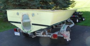
I was directed here by a friend. I am currently restoring a 1967 Donzi Ski-Sporter.

In 1987 a previous owner upgraded to a 310hp Volvo engine/290a drive.

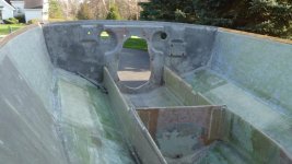
I took the transom shield assembly off yesterday (as the last piece of hardware on the hull) in preparation for taking the boat to the painter.

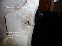
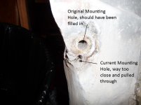
I found that when they installed the new outdrive, the hole that had been cut originally, caused the middle two mounting bolts to be at the very edge of the cutout, such that the transom was effectively "crushed" when they tightened those 2 bolts.

I am looking at a couple of solutions, both of which would be aided greatly by having the template that is used for a new installation.

I have access to a large format plotter, so I could print to actual size if someone had an electronic version of this template.

Thank you in advance for any help!

Bill
 
Re: Installation template for 290A outdrive

Bill, apparently you must sign in to view the images. Can you post them for us?

This may be premature, but I find it difficult to imagine the "Shield" flexing or crushing as you describe.
Keep in mind that the top of the Shield will be torquing AFT, and the lowest section of the Shield will be pushing FWD on your transom when under power!
Those two areas are of your greatest concern, IMO.
Granted..... the center bolts/studs are important!

What is it that you are wanting to do with a template?
Is this boat close to needing a structural transom core replacement anyway?
(had to ask!)

BTW, if you are near a boat salvage yard, and if they have a hull that had a 290 drive removed, and if the hull is to be scrapped out, you may be able to cut the transom from that boat, peel the core material away, and have a nice fiberglass template.
Been there/done that!

Or, you do a tracing around that cut-out using P-lam (Formica for example)!
This would give you a nice ridged template!


.
 
Re: Installation template for 290A outdrive

I hate to say it, but solid plywood cannot be collapsed by overtightening a transom shield bolt. It can be collapsed if it is rotten. My guess is that the transom is rotten which is causing your problem. I would check that out before going any further.


Good luck and have a great day,

Rob.
 
Re: Installation template for 290A outdrive

The transom is fine on the outside.

Inside is where it got "crushed."

I want the mounting template to create a "gasket" of sorts out of 3/8" thick steel to fit around the inside of the hull, so the transom shield will be pulled/tightened against the steel, rather than further crushing the wood in the transom.

There is no distortion on the outside of the hull, and the holes have plenty of room around them. It is just on the inside of the transom where there is a problem.

Hopefully the pictures will help. Sorry, I didn't realize you had to sign in to see pictures at the other site.

Bill
 

Attachments

  • Stbd Transom Ctr hole S.jpg
    Stbd Transom Ctr hole S.jpg
    68.8 KB · Views: 345
  • Port Side Ctr Hole S.jpg
    Port Side Ctr Hole S.jpg
    69.4 KB · Views: 277
Last edited:
Re: Installation template for 290A outdrive

I hate to say it, but solid plywood cannot be collapsed by overtightening a transom shield bolt. It can be collapsed if it is rotten. My guess is that the transom is rotten which is causing your problem. I would check that out before going any further.


Good luck and have a great day,

Rob.

I think once yo see the pictures, you will see what the problem is. The wood is actually dry and in good shape, but where they drilled the hole, there isn't much wood to pull against. Picture drilling a hole so 1/3 of the drill bit's diameter was outside of the material being drilled through.

Then you insert a bolt, and tighten a nut down on the other end. This is what happened with the transom.

Bill
 
Re: Installation template for 290A outdrive

Bill, looks like the boat builder took a short cut on this transom core. It is a partial structural core only.
If this hull is of any size, and if the engine is of any horse power, I'd be replacing this will a more full structural core..... one that extends further to Port/Stbd and top!
Just my opinion.... but that's what I'd be doing!

Or you bridge both of these with a metal piece on the inside, of which would involve two additional SS carriage bolt heads on the exterior of the transom.
The plate will support the the OEM washer/nut for the two center transom mounting studs (one each side)!

I don't mind your steel plate idea, but what an over-kill for just the two center studs/nuts/washers! To do it correctly, it would be a water jet cut piece of SS..... and SS should be of the correct type to be structural!

.
 
Re: Installation template for 290A outdrive

Thanks for the ideas.

The boat is only 16 feet long. It does have a 1987 Volvo 310 hp engine in front of the Volvo 290a outdrive. But the boat isn't that heavy.

The existing transom, which was working fine, and I only took it the transom shield off because I am having the boat painted, has worked fine since April 1967, when the boat was manufactured.

I agree that the best solution would be to re-core the transom, with a larger, more complete area, but I don't think this one is that bad.

I replaced the stringers in the boat, and redid some structural things on the deck, and was looking to reinforce this area. I thought the 3/8" gasket idea would be just fine, acknowledging there isn't that much stress on the "middle" studs.
 

Attachments

  • Transom Inside Shield off S.jpg
    Transom Inside Shield off S.jpg
    71.6 KB · Views: 360
  • Transom shield off outside S.jpg
    Transom shield off outside S.jpg
    66.6 KB · Views: 787
Re: Installation template for 290A outdrive

I appreciate all the observations and suggestions.

I am going to assume no one has a 290 mounting template in digital format.

Time to expand my search.

I would prefer to use the exact cutout shape, rather than guess at what it should be.
 
Re: Installation template for 290A outdrive

A full profile plate to backup the hole pattern is probably overkill. As pointed out in other posts, the only holes under any real stress (including reverse operation) are the top and bottom set. The purpose of the center set is to make sure that the gasket/O ring is compressed properly. Generally, bolt holes are supposed to be at least one to one and a half hole diameters from the edge of the material, and as you can very well see, not doing this results in "tear out". If it was my boat, I'd just cut a pair of rectangular plates about 2" x 4" as oversized washers (clamping plates) from 1/4" stainless and forget about a full profile one. It won't buy you anything (unless you have transom structural problems and it would still be problematic). More importantly... the inner surface of the transom in the area of the center holes needs to be relatively flat. The clamp plate needs to be "bedded" to the transom with some non permanent bedding compound. There are tens of thousands of boats out there w/Volvo drives where the only "clamping surface" on the inside of the transom is a washer. All you need to do is spread (bridge) the clamping force of the center bolts to a structurally sound area of the transom's surface.
 
Last edited:
Re: Installation template for 290A outdrive

sandkicker,

That is pretty much what was in there. Someone had made some 3/8" thick rectangular plates a little smaller than the 2" x 4" you suggested.

Other than it not looking very good, there weren't any problems with it.

Having gone through the effort I have so far to rebuild this boat, I thought I might take the opportunity to improve this particular issue, both structurally, and cosmetically.

Thank you!
 
Re: Installation template for 290A outdrive

I took a closer look at your photos... One question... Which hole is the correct one for the drive collar?
 
Re: Installation template for 290A outdrive

In the starboard and port inside transom pictures, the 290 Transom shield uses the holes labeled "current."

They are the holes that are right next to the edge of the wood. The other holes are what the previous drive (I'm guessing an Eaton) used.
 
Back
Top