Logo

Bf100, nonpower under load.

Sam.doss

New member
Hey everyone, first time poster here.

i have a Honda BF-100 that I bought a few months ago and it has one issue that I cannot figure out.it has no power under load, when you put it in gear it does fine but when you increase the throttle the rpms basically don’t change and then bog down, doesn’t bog it down enough to make the motor cut off, just has no power.

this is what I have done so far;
checked compression 125psi both cylinders
new spark plugs
new fuel lines and filter
took carburetor off and cleaned it throuroghly.
ran some sea foam through it
Nothing I have done has changed the issue at all.

Motor or model number is B100S-1702995

Any help or advice would be much appreciated!!
 
Hi Sam,
Sorry you're having trouble.

First, do you have a shop manual? They a widely available for this model and it's a handy reference and specifications.

The first things that come to mind with low power are:
Fuel starvation
Valve timing and adjustment.
Ignition timing/spark advance

For the fuel side, carb cleaning usually helps. Sometimes a passage doesn't get cleaned properly or something gets overlooked. One thing to check straight away is the fuel tank vent.
Is it fully open? If so, is it clean and venting the tank properly?
Are your supply hoses flexible and soft? No cracks where air can enter? All connectors tight?
Quick coupler at tank and engine fully engaged and locked?]
I know this is all basic stuff but I don't know your level of experience so I have to ask.

Early models had breaker points and a condenser while later ones use CDI. Which one do you have?

When you cleaned the carb, did you fully disassemble and inspect the parts? There's not much to these but dirt hides in the smallest places. There should be two atmospheric vents. Are they clear and clean? Did you remove and clean the slow jet? Did you spray the slow and main air jet passages and look at idle, transition and high speed orifices for spray coming out?
Did you "backflush" those orifices? Did you inspect the emulsion tube for cracks?
Does the float valve move easily and smoothly in it's bore?

Get back with your answers and we can go from there. If some or all of this is Greek to you, that's ok, we can get through it. I just need to know how you approached this to help try and figure out how to procede.
 
Thank you so much for your response!

first off the carb has been removed and cleaned twice.
the second time that I cleaned it I did as you said, I cleaned every passage nook and cranny, ensuring that each vent or passage flows in every direction possible. I fully disassembled as much as I could and cleaned everything. the float operates perfectly and seals and opens as it should.

All the fuel fuel lines and the tank are brand new but I had been running it with the tank lid open just to be sure that vapor lock wasn’t the issue.

The only thing on your list that I didn’t know what I was looking for was whether it had breaker points or a cdi? What do I need to look for? I’m going to guess it has breaker points because from looking at the CDI for that model on eBay I don’t see one on my motor.The spark plug wires run to several places but one of them is a black cylinder about 2” in diameter and 3” tall?

I don’t know a ton about motors but I’m very mechanically inclined (Mechanical engineer by degree) so I will try to be as informative as possible!
 
That black thing is the ignition coil.----Both plugs fire at the same time.-----Do you have spark that will jump a gap of 1/4" or more, yes or no ?-----Is there a rubber plug on top of the cam pulley?----That may hide the points if so equipped.
 
Sorry guys, I was wrong. After further investigation I realized it has a CDI.

imagejpeg

imagejpeg
 
I couldn't open the photos for some reason. If it had points, they would be where racerone said....under the cover on the cam sprocket. If it's CDI, that's also the location of the pulsar. The pulsar is what sends an electrical signal to the CDI to tell it when to fire the black cylinder with the spark plug wires...or, the ignition coil.

Sometimes things go bad under that cam cover. The mount screws for pulsar can get loose and cause the signal to be corrupted and dirt and water can get in there and generally gunk things up and cause rust to form. This too can skew the signal to the CDI. It's a good idea to just take the cover off and make sure the pulsar is secure and everything is neat and tidy in there. Make sure the wire isn't missing insulation and is not corroded or frayed. Inspect the little seal the wire goes through and see that can keep dirt and water out. If it's missing or in bad shape you can seal things up using SENSOR SAFE silicon.

You didn't say if you had a manual so I'm guessing no. When the pulsar cover is off, I can send you some test specs for checking with an ohmmeter. I would look them up now but it is bedtime for me n the dog.
 
Last edited:
Also get a spark tester it will make your job easier , the resistance for the pulse coils should be between 108 to 132.
 
Useing a vacuum gauge is another place to start it will give you an indication of more or less and overhaul condition of your motor it will even tell you if the valve timing is out without stripping anything.
 
Not sure if you're still there, but if you pulled the cap on the cam pulley and everything looks in order, you can easily check engine timing by making sure the punch mark on the cam pulley lines up straight across from the "T" stamped in the crankshaft pulley when the valves on on #1 (top) cylinder are closed. You will need to pull the valve cover to do this but it comes off fairly easily.
 
Not sure if you're still there, but if you pulled the cap on the cam pulley and everything looks in order, you can easily check engine timing by making sure the punch mark on the cam pulley lines up straight across from the "T" stamped in the crankshaft pulley when the valves on on #1 (top) cylinder are closed. You will need to pull the valve cover to do this but it comes off fairly easily.


From doing some some research I believe timing and valve clearance is my issue.

I have checked the plugs and they will jump a 1/4” and also have my fingers a little bit of a buzz, I guess that’s normal.

i received this information on how to time and adjust the valve clearances from someone. Can any of you confirm if this is the right procedure to follow;

[FONT=&quot][FONT=&quot]B100 Valve and timing set;[/FONT][/FONT]
[FONT=&quot][FONT=&quot][/FONT]
[/FONT]

[FONT=&quot][FONT=&quot]Remove the spark plugs. [/FONT][/FONT]
[FONT=&quot][FONT=&quot]Remove the valve cover and back off all the valve adjustment screws and locknuts.[/FONT][/FONT]
[FONT=&quot][FONT=&quot]Find the T line on the flywheel.[/FONT][/FONT]
[FONT=&quot][FONT=&quot]Find the imprinted dot on top of the cam pulley and align it with the identical looking dot just in front of it stamped in the head.[/FONT][/FONT]
[FONT=&quot][FONT=&quot]Do this all by hand and if you feel any hard resistance STOP!![/FONT][/FONT]
[FONT=&quot][FONT=&quot]Re-Install the timing belt.[/FONT][/FONT]
[FONT=&quot][FONT=&quot]Adjust the valves ,middle two are intake and adjusted to .004 to .006 inches,[/FONT][/FONT]
[FONT=&quot][FONT=&quot]outer are exhaust with a .006 to .008 spec.[/FONT][/FONT]
[FONT=&quot][FONT=&quot]Start with the dot and timeing pulley aligned.[/FONT][/FONT]
[FONT=&quot][FONT=&quot]Thats #1.[/FONT][/FONT]
[FONT=&quot][FONT=&quot]Then move the cam pulley 180 degrees and that is #2 TDC.[/FONT][/FONT]
[FONT=&quot]

Once again thank you guys so much for taking the time to help me.[/FONT]
 
Well, other than telling you that you don't need to remove and re-install the timing belt, which you probably already know, that tutorial should get you there. That procedure is technically correct and sound.

Not quite the way I go about it but if you can work with this, there's no need to confuse you with "my way".

The important thing is to HAVE FUN!
 
I’m actually really enjoying this process, gives me a chance to learn about engines and how they work (or atleast this one) I know it’s a good motor it just has a few quirks.

first off I’ll make sure it’s aligned and check the valve clearances before I do any adjusting.

Do you check them with a feeler guage?
 
Yes, feeler gauge. You will likely find the adjustment wants to "drift" from what you set it at when you double check after snugging down the lock nut. You will need to learn to compensate for this to obtain an accurate clearance.

I say "snug" the jam nut because they only need to be tight enough so that they won't back off and not super tight. It's important that they can't back off but overtightening only leads to problems breaking them loose next time.

Good luck
 
The bf 75 and bf 100 have the same valves standard cam lift for the bf100 intake is 25.2 mm then from serial no 1000004 to 1199999 cam lift is 25 mm and when i compared your valve clearances its different to the manual check your cam lift size just to be on the safe side .
 
Well, it's NOT 25mm but tegwini does make a good point. The actual measurements are:

0.06mm to 0.10mm OR 0.002 in.TO 0.004 in.

This is for BOTH intake and exhaust valves. This I read directly from my "old" engine manual. The specs you were given by someone else were from the later model twins and I confess I missed that when I OK'd what was written because it looked "RIGHT".

There's no harm to the engine by adjusting them loose but it could effect performance and THAT'S what you're trying to solve! My apologies.

It WILL damage the engine if you get them too tight so make your adjustments more to the middle of the spec. range.

.
 
Last edited:
Thank you jgmo your statement is 100% correct about the valve clearances , we sometimes miss the finer things the most common cam lift size used in the bf 100 is 25.2 mm there are bf 100 cam lifts at 25mm its always wise to compare cam lift sizes its so easy to make a mistake. :)
 
Well, it's NOT 25mm but tegwini does make a good point. The actual measurements are:

0.06mm to 0.10mm OR 0.002 in.TO 0.004 in.

This is for BOTH intake and exhaust valves. This I read directly from my "old" engine manual. The specs you were given by someone else were from the later model twins and I confess I missed that when I OK'd what was written because it looked "RIGHT".

There's no harm to the engine by adjusting them loose but it could effect performance and THAT'S what you're trying to solve! My apologies.

It WILL damage the engine if you get them too tight so make your adjustments more to the middle of the spec. range.

.


Thank you for double checking!
i plan to do these adjustments this weekend and I will update you on progress or if it solves it.
 
Thank you for double checking!
i plan to do these adjustments this weekend and I will update you on progress or if it solves it.

ALRIGHTY.
tonight I went out to my shed armed with a light, and a heater and this is what i found.

#1 I messed up by taking the timing belt off before checking all the marks to see if it was out of time in the first place.

#2 So I lined everything up (T-line facing pull starter mount closest to cam pully, and cam pully outside dot lined up on the raised line on the head.) I double checked this by rocking the cam pully back and forth (with the belt off) tapping the valves against the piston,making sure it was at the top of its stroke.

#3 there was no clearance, if anything the valves have been slightly open and never close. I’m not sure how much but I know at TDC the valve screws were very tight and no clearance. (I watched the valve spring tension being let off slightly as I backed the screws off, easily each valve could have been open several thousands or more.) Used my .005 feeler and once tightened they were at .004.

took the time to go ahead and change my engine oil. And started draining my foot oil to find out it’s milky as my cereal... so it looks like I have another issue to investigate...

tomorrow i I plan on starting it up, I’ll let you guys know what it does.
 
These old gals are pretty hardy. Hopefully you don't have any damage. The fact that it always started and idled ok is a good indication that the engine is still sound.

Too bad now you have to learn about gearcase sealing. THAT can be a real pain. The case has to be able to hold a slight positive pressure as well as a very slight vacuum to keep oil in and water out.

Good luck with the "dyno test" ;>)


So so I took the motor outside to my tank and started it up.

first off I noticed that the motor idles much higher now but smoother than it did before.

the only downer is that my water pump seems to only be working intermittently now? Water comes out and then doesn’t then does or just trickles (it’s about 30 degrees outside but I didn’t let it run long)

the good old news is I shifted into gear and throttled up quickly and it instantly blew all the water out of my tank (of course I turned it off immediately)

the only issue now now is the idle seems to be high and when I try to turn it down it kills the motor. But I did notice that when it does pump water the idle is much much better..

so so it looks like I’ll be tackling the water pump next. Can anyone talk me through that?

THANK YOU THANK YOU THANK YOU FOR HELPING ME!
you guys are a godsend for sure!
 
You can be "talked through" pretty much any repair on these little outboards but, honestly, I feel the absolute best advice I can give you is to buy the workshop manual.

They are available on Amazon for about $30 and, sometimes, you can pick up a used one on eBay or Craigslist for $10 or $15. There are graphics for most operations including the water pump and they depict where different length bolts go and such.

The valves being adjusted WAY too tight is a glaring example that you can't trust anything that was done previously so, without the manual, you may put something back the way it came apart but it could be all wrong!

The water not pumping well intermittently could be indicative of the impeller installed the wrong way. This is a classic example of what I'm talking about.

I'm sure, with your engineering background, you know the value of equipment specific documentation as well as the meaning of rtfm ;>)

Just sayin'
 
Last edited:
You can be "talked through" pretty much any repair on these little outboards but, honestly, I feel the absolute best advice I can give you is to buy the workshop manual.

They are available on Amazon for about $30 and, sometimes, you can pick up a used one on eBay or Craigslist for $10 or $15. There are graphics for most operations including the water pump and they depict where different length bolts go and such.

The valves being adjusted WAY too tight is a glaring example that you can't trust anything that was done previously so, without the manual, you may put something back the way it came apart but it could be all wrong!

The water not pumping well intermittently could be indicative of the impeller installed the wrong way. This is a classic example of what I'm talking about.

I'm sure, with your engineering background, you know the value of equipment specific documentation as well as the meaning of rtfm ;>)

Just sayin'


Point taken, manual ordered. Thanks again for all your help!
 
Good move Sam! While this little manual isn't the most "comprehensive" one ever printed, it gets you there for the most part. We have questioned a few of the electrical ohm values in it and I have made notes in mine with different values. I will be happy to share them with you but since you have a running engine, you can do some empirical testing on your components and form your own custom baseline so you KNOW what works.

All in all it's one of the essential tools for DIYing on the Bf 10 and 7.5.
image2.jpgimage1.jpg

I hate to bother you guys one more time.

I was able to find the shop manual for my motor online and it doesn’t answer one question I have.

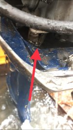
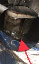
looking down below the motor I can see the exhaust pipe.
i noticed that there is water squirting directly out of the front. (It’s coming from the space between the two metal flanges)

My questions are;
#1 is this hurting anything?
#2 does the water pipe from the impeller run to this area?

I’ve looked through the shop manual and I cannot find what the water pipe that comes up from the foot to the extension case connects to in the oil case. Is the water running through a passage built into the exhaust pipe?:confused::confused:
 
You're NOT bothering anybody HERE! Trying to help each other figure out our outboard problems is EXACTLY why all of us joined up!

Yes, the tube from the water pump goes up through the extension case and "plugs in" to the oil case. There is supposed to be a little ledge that the tube pushes up against that acts as a seat for the rubber seal at the end of the tube and also serves as a stop for the tube.

Many problems can occur at this "junction". The easiest to deal with is if the seal has gone bad.

But corrosion and vibration can erode the aluminum in the bottom of the oil case and that little round ledge that supports the water tube end and allows the rubber grommet to form a water tight seal can be completely gone! I have built up a new "socket" with epoxy and have it work well.

However I don't think that problem would have water pooling in the oil case like it is in the photo.

If you look at the back of your manual you should find a simple diagram showing the cooling system and water flow. You will see the water comes from the pump, up through the case, into the bottom of the block and to the thermostat housing. It then can flow through the cylinder head if the thermostat is open.

But some of the water ALWAYS flows past the thermostat housing and joins the exhaust gasses to flow out the extension case. At the same time, a small part of this flow is directed to the outlet for the tell tale stream.

Your photo makes me think that there is a leak either from the bottom of the tstat housing or in the tubing for the tell tale.

One other possibility is that the oring between the engine block and the oil case has failed.

The oil case bolts up to the engine block and seals with a fiber gasket. There is a small cutout in that gasket for the water supply oring to sit in. Therefore, the only way to access that oring is to remove the powerhead.

If that oring fails it can also allow sea water to get into the oil sump and contaminate the engine oil.

I hope it's not that. But, if it is, it's really not that bad of a job. At the end of replacing that oring....and thus the oil sump gasket....You will have completely disassembled the outboard.

Not a bad thing really. You then have an opportunity to clean sump, clean the filter, check the oil pump and inspect the engine bearings...
If you want to. It will all be opened up accessible at that point and you could actually take advantage of the situation if you have the time and the funds for the additional parts.
 
Last edited:
Back
Top