Hello,
I have just bought a 400 Ah LiFePo4 battery for my performance sailing catamaran. I will have multiple charging sources most of which programmable. The exceptions are the 2 Hondas BF20D which when the battery is charged can put out up to 14.9 volts with a 12 A max charge. The battery max charge voltage is 14 V so if the battery is charged and the engines need to be run there is a risk of overcharging and setting off the Battery Management System safety relay that will cut off the charging bus bar and possibly fry the alternators.
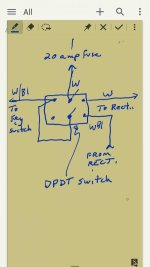
The idea is to have a relay controlled by the battery monitor that will interrupt the exciter coil or a wire in the regulator/rectifier when the state of charge is 100%. By Looking at the enclosed diagram from the service manual I guess the Y/Bl yellow black wire that goes from the regulator to the CDI unit seems a good candidate. The exciter coil is directly connected to the CDI so there are no direct connection between the regulator and the exciter coil. The other wires on the regulator have other functions. W (White) regulated dc to the battery, the 2 greys are unregulated ac into the rectifier bridge, White black is positive in from the ignition switch. The strange thing is that the the CDI unit is powering the exciter. I suspect that the Y/Bl is sensing the voltage generated by the charging coil. If that is the case then if I open the circuit it may actually crank up the exciter current. So maybe cutting the exciter coil circuit may be a better option.
I hope some one here is familiar with this engine charging system.
CheersView attachment Charging system.pdf
I have just bought a 400 Ah LiFePo4 battery for my performance sailing catamaran. I will have multiple charging sources most of which programmable. The exceptions are the 2 Hondas BF20D which when the battery is charged can put out up to 14.9 volts with a 12 A max charge. The battery max charge voltage is 14 V so if the battery is charged and the engines need to be run there is a risk of overcharging and setting off the Battery Management System safety relay that will cut off the charging bus bar and possibly fry the alternators.
The idea is to have a relay controlled by the battery monitor that will interrupt the exciter coil or a wire in the regulator/rectifier when the state of charge is 100%. By Looking at the enclosed diagram from the service manual I guess the Y/Bl yellow black wire that goes from the regulator to the CDI unit seems a good candidate. The exciter coil is directly connected to the CDI so there are no direct connection between the regulator and the exciter coil. The other wires on the regulator have other functions. W (White) regulated dc to the battery, the 2 greys are unregulated ac into the rectifier bridge, White black is positive in from the ignition switch. The strange thing is that the the CDI unit is powering the exciter. I suspect that the Y/Bl is sensing the voltage generated by the charging coil. If that is the case then if I open the circuit it may actually crank up the exciter current. So maybe cutting the exciter coil circuit may be a better option.
I hope some one here is familiar with this engine charging system.
CheersView attachment Charging system.pdf