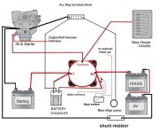
So I will be using a dual battery system. I will have each of the positive lines go to a transfer switch, so that is easy enough, but here is the problem.
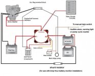
I am assuming that the proper way to wire the negative side is battery 2 negative to battery 1 negative to engine. I already have a thick negative cable running to the engine. So that means one of the batteries will have TWO negative cables running to it (one going to the engine, and one coming from the other battery).
That said, is there a special terminal that supports two thick gauge battery cables on a single terminal??? I have had a hard time locating such a thing.