Logo

Honda b75 ignition test procedures

flboat-er

New member
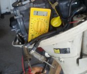
Forgive me if the procedures have been posted already. I've searched for several hours with no luck. There seems to be others asking the same question but I dont see a distinct and consice answer. I have the service manual, however its pretty vague and gives readings for serviceman using a Honda test unit.

I need specific specs to troubleshoot a no spark condition. Expected multimeter readings and procedures for testing the following:
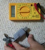
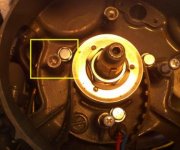
primary coil
Charging coil
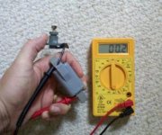
Points -although I'm pretty sure I know how to test these and after a good cleaning they seem in spec.
Condenser
Ignition coil

I think I know how to test the primary and charger coil and I believe they are within spec, but want to double check. I'm leaning toward ignition coil or condenser, but not sure. Don't want to buy extra parts doing the trial and error method.
 
Howdy, welcome aboard the forum.

I don't think I've ever seen a B75 live and in person. I checked the Helm Inc. site for what the manual looks like though and they list the same one I have for the BF75, BF100 and BF8A. So, that's what I'm referring to here.

The tests indicated in MY manual are all done with an ohmmeter. There has been some discussion here in the past about the specifications given in the book as being different from empirical testing done on "known good" components. I have made notes on these values and will give you both the printed value and tested value where applicable. And, here goes...

Primary coil resistance: 2 ohms. measured between the two wire terminals.

Charging coil resistance: 0.13 ohms +/- 10% measured between the two wire terminals.

Ignition coil secondary winding as measured through the plug caps of the two plug wires when disconnected:

NOTE: this test sometimes confuses people because you are putting one probe into one plug wire and the other probe into the opposite plug wire. The reason is that both wires fires simultaneously and are connected to each other internally to the coil. (hope I didn't just confuse you further).

The printed value for the combined plug wires and coil resistance in the book is 8k ohms +/- 20%.
However, I and others, have tested coils from running engines and, I at least, have measured 31.5k ohms for both CDI and breaker point ignitions.

Ignition coil primary windings: Printed in the book is 0.56 ohms +/- 10%. I/we have measured 1.5 Ohms for breaker point coils and 0.8 ohms for CDI coils as measured across the two wire lugs

The condenser should be checked with a capacitor checker. I use a Fluke 87a DMM that has one built in and it is very accurate. The capacitance of the condenser is listed at 0.24 microfarad Any doubt the condition of the condenser though and I would just replace it. The condenser is the weakest link in the chain here and they deteriorate just setting.

The points are simply contacts and should read infinite ohms when open and 0 resistance when closed.

If I did confuse you or if you have any other questions, please ask. That's why we're all here.
 
No.. you didn't confuse. I appreciate your help a lot. I've done so much reading on this motor but couldn't match the readings I found in other posts. I understand the ignition coil firing both cylinders.. I read about that earlier in my research. I need to pick up a capacitor test unit. My guess is that the capacitor is the faulty part since I get readings from the other components but won't be sure until I get the test unit. The readings don't match what I've read in different places so it could still be one of the other components. The problem with just buying one is they are charging 29.00 for one which is pretty high. Should be only around 10.00. Don't want to just throw money at it.

Another question I have is if the bulb for the oil pressure light is burned out will that cause a no spark situation? I bypassed the kill switch with no luck. Also, I read that one plug must be in place with the cap on to test the spark on the other plug. That you can't take them both out and expect spark. Is that true?

Thanks again for all your help. I'm going to do some troubleshooting with the information you gave me this weekend. I'll let you know what I find.


Howdy, welcome aboard the forum.

I don't think I've ever seen a B75 live and in person. I checked the Helm Inc. site for what the manual looks like though and they list the same one I have for the BF75, BF100 and BF8A. So, that's what I'm referring to here.

The tests indicated in MY manual are all done with an ohmmeter. There has been some discussion here in the past about the specifications given in the book as being different from empirical testing done on "known good" components. I have made notes on these values and will give you both the printed value and tested value where applicable. And, here goes...

Primary coil resistance: 2 ohms. measured between the two wire terminals.

Charging coil resistance: 0.13 ohms +/- 10% measured between the two wire terminals.

Ignition coil secondary winding as measured through the plug caps of the two plug wires when disconnected:

NOTE: this test sometimes confuses people because you are putting one probe into one plug wire and the other probe into the opposite plug wire. The reason is that both wires fires simultaneously and are connected to each other internally to the coil. (hope I didn't just confuse you further).

The printed value for the combined plug wires and coil resistance in the book is 8k ohms +/- 20%.
However, I and others, have tested coils from running engines and, I at least, have measured 31.5k ohms for both CDI and breaker point ignitions.

Ignition coil primary windings: Printed in the book is 0.56 ohms +/- 10%. I/we have measured 1.5 Ohms for breaker point coils and 0.8 ohms for CDI coils as measured across the two wire lugs

The condenser should be checked with a capacitor checker. I use a Fluke 87a DMM that has one built in and it is very accurate. The capacitance of the condenser is listed at 0.24 microfarad Any doubt the condition of the condenser though and I would just replace it. The condenser is the weakest link in the chain here and they deteriorate just setting.

The points are simply contacts and should read infinite ohms when open and 0 resistance when closed.

If I did confuse you or if you have any other questions, please ask. That's why we're all here.
 
Well, it's getting harder to do but you can still find a condenser replacement at an auto parts store IF YOU CAN FIND A COUNTER PERSON WITH A BRAIN that is willing to help you. The problem nowadays is that they can't seem to find anything unless you give them a year, make and model to match that condenser. I'll do some checking myself and see if I can't find a source for that at a REASONABLE price. I've been meaning to do that for myself anyway. You will probably find that is much less expensive than buying a reliable capacitor checker. A guy with a meter like mine could check it for you in 30 seconds but, again, finding FRIENDLY help these days can be difficult. If you have a relationship with a local auto shop or even smog test center, those guys usually have a decent DMM lying around.

The oil pressure light should have no bearing on the ignition system as it is an isolated circuit.

What you've been told is only partially correct. Since the coil fires both plugs, you will not get a RELIABLE test result if one plug is left out of the "loop". All the AVAILABLE VOLTAGE from the coil will seek ground through the one plug and a weak coil might actually look good with one plug out. You should take BOTH plugs out, ground both electrodes and then crank the engine watching for spark from both plugs. Be advised, the spark is VERY faint and has led many guys to think that there is none. If you check for spark this way, do it in a darkened room, at night or with a blanket or something over your head and the engine to act as a hood for a "darkroom" effect. I like to just use an inductive timing light hooked to a lawnmower battery. That is the quickest, easiest way to confirm spark on one of these engines.

Some engines were equipped with a neutral safety device that prevents spark from occurring if the engine is cranked while in gear. If yours is so equipped, make sure that is not your problem if you are certain that there is no spark.
 
Ok.. So I tried to work things out this weekend. I tested the ignition coil with an ohms reader set at 200 ohms and got nothing. The only question I have is should I have taken the part off of the engine? See photo of test and reading.


Also, I added a photo of the coils and the breaker points/condenser. I have two wires coming off the charging coil, but only one black wire coming off the primary coil. Assumed I could just touch the ground side of the primary and the end of the wire with the positive ohms reader. Did so and got strange readings seeming to be high, then quickly reduce to zero. I don't believe that I'm testing it properly.. The charging coil seems to be in spec, or close to it if test procedure is to use the two wires as you say.


Still no test on the condenser. At this point feel it's ignition coil and possibly the condenser..


Did I perform the test right on the ignition coil?
 

Attachments

  • Screen shot 2012-09-10 at 5.50.51 PM.jpg
    Screen shot 2012-09-10 at 5.50.51 PM.jpg
    30.6 KB · Views: 541
  • fullMotorViewSmall.gif.pdf
    250.8 KB · Views: 564
  • chargingPrimaryCoilView.pdf
    199.3 KB · Views: 626
  • ignitionCoilView.pdf
    211.2 KB · Views: 708
Last edited:
One other thing I should have mentioned. The ignition coil has two plug wires coming from the main coil. I tried to remove the wire to see if the coil is good and possibly it's just one or both wires or caps, but could not remove them. It seems they cannot be taken off of the coil. Is this true or am I not putting enough effort into it. I don't want to damage anything.
 
After looking at the photo for your ignition coil secondary winding test, I have two questions. Did you sand paper the nails you are using for test probes so that there is a good connection? And, why did you use the 200 ohm scale when the specification is 8 THOUSAND ohms? Set your meter on the 20 kilo ohm setting to get a reliable reading.

Not sure what you're getting with that primary coil. I just sent you what was written and depicted in the book. I haven't had any problems with these primary coils so I don't have any tricks to share. I do see though, studying the wiring diagram, that it shows only one wire going to the points and condenser with the other wire terminated at the mounting under the flywheel.

You may need to unbolt and take it off the outboard to find the other end of the coil. If it is terminated internally then it will be grounded through the mounting bolt and simply touching the one wire with one test lead and placing the other lead on the coil's "frame" should yield a reading. THIS is where you would use the lower ohm scale to read 2 ohms.

Keep us updated as to what you find.
 
Hey jgmo.. I appreciate your determination to help me. If there is anything I can do in return I would be glad to do it.

In regard to the sanding of the nails. No. I'll try doing that. I used the 200 ohm scale cause I am just starting to learn how to use the tool.. I'll change it to the 20 k setting and try it again. I'll also remove the primary and see what readings I get using the lower scale.

Thanks again and I'll keep you posted.. Hope to try again sometime this week or weekend.
 
The only reward I need is to hear you've sorted out your problems. Keep plugging away and we'll see if we can't get you out on the water soon. And, as an added bonus, both of us might learn a thing or two along the way.
 
Well, If you ever get to florida.. let me know.. I'll take you out on my 24 foot pontoon.. project boat with a 70 johnson I took out of the crate myself in 2001.. I know that motor inside and out. The new one replaced an old 1979 johnson still running well, but looked like hell from the salt water. I hated manually pulling that thing up and putting a 2 x 4 in the hinge to hold it up. Now it sits in my garage as a parts motor for my new one.

Anyway, I did what you recommended.. I used a grinder to shine out both ends of those nails and put the ohms reader on 200k. I got a reading of around 69 to 70. Does that mean it's good? note: I tried the 20k setting and it still wouldn't read..
 
Last edited:
Thanks for the invite. I was just telling my wife that I get invitations from all over the world because I try to help guys fix their boats. She said "well, lets take someone up on it" I told her though that we were so broke we couldn't get to most places and, if we did get there, the people would have to adopt us and take care of us because we sure as heck can't afford to get back! But, again, thank you!

As to your coil, the answer is...I don't know. The specification is 8k ohms +/- 10%. That puts yours just outside the window. However, I don't know the quality of that meter you're using and resistance readings are dependent on many variables. Like temperature and even humidity. So, a little meter error and a cool day and you get a "iffy" reading. At this point I'm going to say, though, that I would not condemn the coil based on that reading. Let's call it OK and move on.

That is only half the test for ignition coil. You have to test the primary resistance too. The specs and also my own "real life" readings are listed above. I believe your coil should measure 1.5 ohm across the primary connections. Check that and get back to me with the reading.

Here's another way to "real life" check a coil like that. Because you really only want to know "will it fire my plugs"? Right?

Take two known good spark plugs, properly gapped, and put the wires on them. Use two "jumper" wires with large alligator clamps on each end to connect the bodes of the spark plugs to the negative post of a 12volt battery. Take another jumper wire and connect the + (or bat.) terminal of the coil to the positive terminal of the battery. Take a fourth jumper wire and connect to the - (or neg.) terminal of the coil BEING VERY CAREFUL NOT TO TOUCH ANYTHING WITH THE OTHER END OF THAT WIRE! protect and insulate the end of that wire until you are ready to do this:
Take the loose end of that wire and "swipe" it or "spank" across the negative terminal of the battery. The contact must be ever so brief. As you do this, the coil should fire the plugs if it is sound. DO NOT DO THIS MORE THAN A FEW TIMES since you are fully saturating the coil and could stress it if you keep doing it. A darkened room with someone else to watch the plugs fire while you are manipulating the wire will yield better findings. But, if the coil is good you should be able to hear the plugs fire...pop pop.

You will need to fabricate four jumpers if you want to try this "good old boy" coil test.
 
You're richer then most when it comes to friendships. That's what counts. The older I get the more I realize that. I tell ya, if I knew back in my teens what I've learned through life, I would have changed a few things around.

Anyway, As for the advice, I'll try that this weekend. I'll keep you posted.
 
Ok.. Sorry for the delay in me getting back to you. Hope you're still around.

I tested the primary coil after I took the part off the motor. There is only one black wire coming out of the part. When I put the ohm reader's negative terminal on the non wire side of the coil and the positive on the end of the wire I get nothing.. No reading. The place that I'm contacting is very clean. See pic.

If I touch the ohm positive and negative terminals on each side of the primary coil (not on the wire) I get a .2 when the unit is on the 200ohm setting (I get a .1 when I touch the terminals together to gauge accuracy). I'm wondering if I have a bad wire which probably means I've got to buy a new part.. What do you think.. See pic>


One other note: When removing the primary, one of the screws was so tight I couldn't do anything but drill the head off and use vice grips to turn it out. The bad part is when turning it out it broke off so I believe the screw seemed to almost be welded in the whole. Is that uncommon? Since the bolt hole is not flush with the housing I don't think I can drill a larger whole and insert new threads. Might have to buy a new one. Not sure if there is another way to fix it. Your thoughts?
 

Attachments

  • PrimaryCoiltestWithoutReading.jpg
    PrimaryCoiltestWithoutReading.jpg
    19.6 KB · Views: 447
  • PrimaryCoilTestWithReading.jpg
    PrimaryCoilTestWithReading.jpg
    19.7 KB · Views: 358
  • BrokenScrew.jpg
    BrokenScrew.jpg
    19.8 KB · Views: 343
Last edited:
Yeah, well, er, uh...I don't know.

It's hard for me to tell exactly what you're doing looking at these pics. But, it SEEMS as if you're not doing it right.

In the first pic it looks as if you are simply putting one probe in one mounting hole of the armature bar and the other lead in the other hole. The reading on the meter would tend to back that up as it shows little to no resistance.

In the second pic, it looks as if you have the black lead tip in a mount hole of the armature bar but I'm not sure what you are touching with the red lead. Is it the screw? Anyway, you should be touching the ring terminal of the black wire shown and EITHER mounting hole of the bar. Do that if you haven't already and get back to me.

As far as the broken screw is concerned, I see no alternative but to drill it out.... CAREFULLY!

The way I do those is to get out my trusty Dremel tool and chuck up a 1/8 inch CARBIDE, BALL SHAPED, BURR.

With this marvelous, worth it's weight in gold, indispensable little burr tool you can position yourself over the hole, get comfortable and, like any good dentist, carefully true up the end of that screw so that you form a little "bowl" on the end of it that will accept a tiny cobalt or titanium tipped drill to start a small pilot hole.

During this process, spray a bit of PB BLASTER on it and let the heat of grinding and drilling help the penetrant oil work it's way down into the threads. I finish holes like these with my 3/8" drill motor and a left handed, COBALT twist drill about the same size as the screw. Most of the time the screw comes out as soon as I start drilling with the lefty bit. If not, keep putting on the Blaster and use the smallest E-Z out you can find as soon as you can get a bite with it.

Yes, I realize that you will not be equipped with all this stuff but that's what it takes to get it done. Tools are not expensive, they're priceless.

Or, any machinist worth his salt will get it out for you. For a handsome fee of course.
 
Hey Jgmo,

Sorry for the delay. Life keeps you busy.. Especially with three children under the age of 7. Anyway, here is my response.

I've attached a better picture of where i was touching the red lead. I don't know where else to touch other then that bolt. What appears to be another connection point is really just a metal tab to stabilize the wire. There is no real connection since that black is a plastic cover to protect the wire.

The broken screw is unfortunate I don't know why that bold would essentially seem like it's welded in place. I can manage resolving that issue. Thanks for your help with that.
 

Attachments

  • primaryCoilWireView.jpg
    primaryCoilWireView.jpg
    21 KB · Views: 275
flboat-er
No worries mate! I chase my 5 year old grandson that lives with me now and I am pretty worn down by 10am! So I know how it is.

Nice photo! Yes, now I can see that you are probing in the right area.

Yeah, it don't look good for that coil. Are you on the lowest ohm scale? Are you absolutely, positively, for sure, sure that you're making good contact with both probes and that the probe sight in the bolt hole is clean and free of paint?

I hate to think of all the times I chased my tail using an ohmmeter when I didn't verify the connections. But, if you've done all that, then it looks as if that coil is open and that does suck because they aren't sold anymore as far as I know. And, I don't know what you might get away with as a substitute.

I don't know if that plastic housing and the coil is all bonded together with epoxy or not. If It isn't, I would not be above carefully cutting the plastic away to see if I could figure out where the open is. I mean, it's just a length of wire wrapped around an iron core. Many times, those tiny wires will break where the terminate or come out of the housing so, if you could find the break, you could just solder it and be back in business. But, I've never tried it.

I don't know where to point you now except to say go to Ebay and see if you can hunt one down there. I see some listed from time to time and I should just buy them when I can but I'm always thinking what if the one I buy is no good? Honda didn't count on these things running forever and I bet they are hoping some of them will just go away so they can sell new ones. What they may not be realizing though in not supporting the old motors is that those old babies MADE their reputation in the boating world and they don't get hurt too bad by having them out there perpetuating the glory. Oh well, just my opinion and it don't seem to count much anymore.

Anyway, I'll keep my eye out for a primary coil and if I run across one, I'll be sure to let you know.
 
Back
Top