Logo

1982 BF100F and similar Rectifier Replacements

I have been trying to locate an alternative to the rectifier assembly 31700-881-000 which is now obsolete.

If I could find one, I would buy one. Since I can't, has anyone found or used and alternative that worked as a replacement?

It is referred to as a rectifier assembly - which I am assuming does some voltage regulation as well - but that I am not sure of.

Any suggestions would be appreciated,

Wayne
 
The rectifier is just a rectifier. The technical term is full wave rectifier. If it were me, i would go to Radio Shack and buy a full wave rectifier (10amp...more than enough current rating). Then wire it into the circuit. Cost of about $3.00. The Radio Shack Rectifier http://www.radioshack.com/product/index.jsp?productId=12625303 The circuit diagram of the engine page 40 http://marine.honda.com/pdf/manuals/31882621.pdf

If you are unsure how to wire it in, check with a local HAM radio operator. Rectifiers and power supplies are basic stuff for HAMs.

Mike


Thanks Mike.

I am very familiar with FW rectifiers and have a few that will do the job sitting on the shelf. I wasn't sure just where they did the regulation and have, confirmed that this is just a rectifier through a friend who is also a Honda dealer. Both of you say the same.

Most of the PS designs I have built put a voltage reg and capacitors after the rectifier, which is why I guessed this might be more than just the FW rectifier. The newer models seem to be combining these (and have tripled the price).

Thanks for the quick response and sources. I hope others can benefit from this as well.
 
AlwaysFixin - It would be a service to other owners if you thoroughly documented you procedure and posted it.

Ok. I did something a little different than was suggested because I chose to use a bridge rectifier that had the rectifiers encased in an aluminum block (which aided in both mounting and in cooling of the rectifiers and because I had some in my parts bin already).

A similar part would be: http://www.radioshack.com/product/index.jsp?productId=12681237

The bridge had 4 connections: +, - and two labelled AC or ~

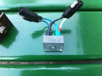
For those not familiar with these devices, the + and - hook up to the connector that proves power out to the exterior engine connector and fuse. I chose to use a slightly different connector than was there originally but if you want to reuse the old one, cut the wires from the old rectifier close to it to give you lots of wire and you should be good to solder the red (the side which goes to the fuse) to to the + on the bridge and the green to the - on the bridge. I installed colored heat shrink tubing over the wires before soldering them so I could slide them over the soldered connection after soldering to shrink on and insulate and identify the connections (red for +, black for -).

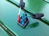
The two AC or ~ connections accept the AC provided by the two blue wires from the motor. Again, if you cut them close to the original rectifier to give you good length, slip heat shrink tube over the wires and then connect these to the two AC or ~ connectors and solder, slide the heat shrink over the soldered lugs and then shrink them, you should be good.

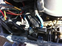
The other thing I did was to drill out the hole in the block a slight bit larger to fit the 6mm screw that held the original rectifier. I replaced the screw with a shorter one - one that stuck out about a 1/4 to 1/2 inch from the new block and then installed this rectifier in place of the old rectifier - of course being careful not to stress the wires too much. plugged the two connectors in as the original had been (blue into blue and red/green into red/green) and I now am back to having power generated to charge my boat batteries and power my running lights.

I have included some photos in the hopes they clarify some of my words.
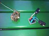
The old and the new parts - I have already soldered on and installed the heat shrink over the solder lugs.A view from the bottom of the new bridge rectifierA view from the top of the bridge rectifier - Notice the blue wires go to the AC or ~ posts.  The red (white in my case) goes to the + and the green (black in my case) goes to the - post.Installed on the motor - With the hole in the middle drilled out to fit the 6mm attachment screw, the new bridge rectifier is now installed and plugged in correctly and most importantly, providing power to my batteries!


I hope this helps some of you get a few electrons out of your old motors (given that Honda has decided to discontinue supplying the original part).
 
Great post! and even better pics! Now lets see how she takes the heat. Thanks for the effort.
 
Back
Top